If this condition is not fulfilled, the assumptions that the angle of I
fault
is close to the angle of Iph or close to the
angle of I2 cannot be considered valid. Under such conditions the Quadrilateral characteristic could significantly
overreach or underreach. To avoid this, the distance protection automatically switches from Quadrilateral to Mho
characteristics to provide stable operation.
3.2.2.2 EARTH FAULT FIXED REACTANCE LINE TILTING
Each zone has an independent setting to set the tilt angle (σ) of the Impedance Reach line of the quadrilateral
characteristic. If dynamic tilting is disabled, the characteristic uses this setting to apply a fixed tilt to the top line.
The tilting angle is with reference to the fault current I, and is defined by:
Tilt angle = setting (σ) =
Ð
Iph/I
The setting range is +/- 30°. A negative angle sets a downward tilt and a positive angle sets an upward tilt.
Operation occurs when the operating current I lags the polarizing current Iph.
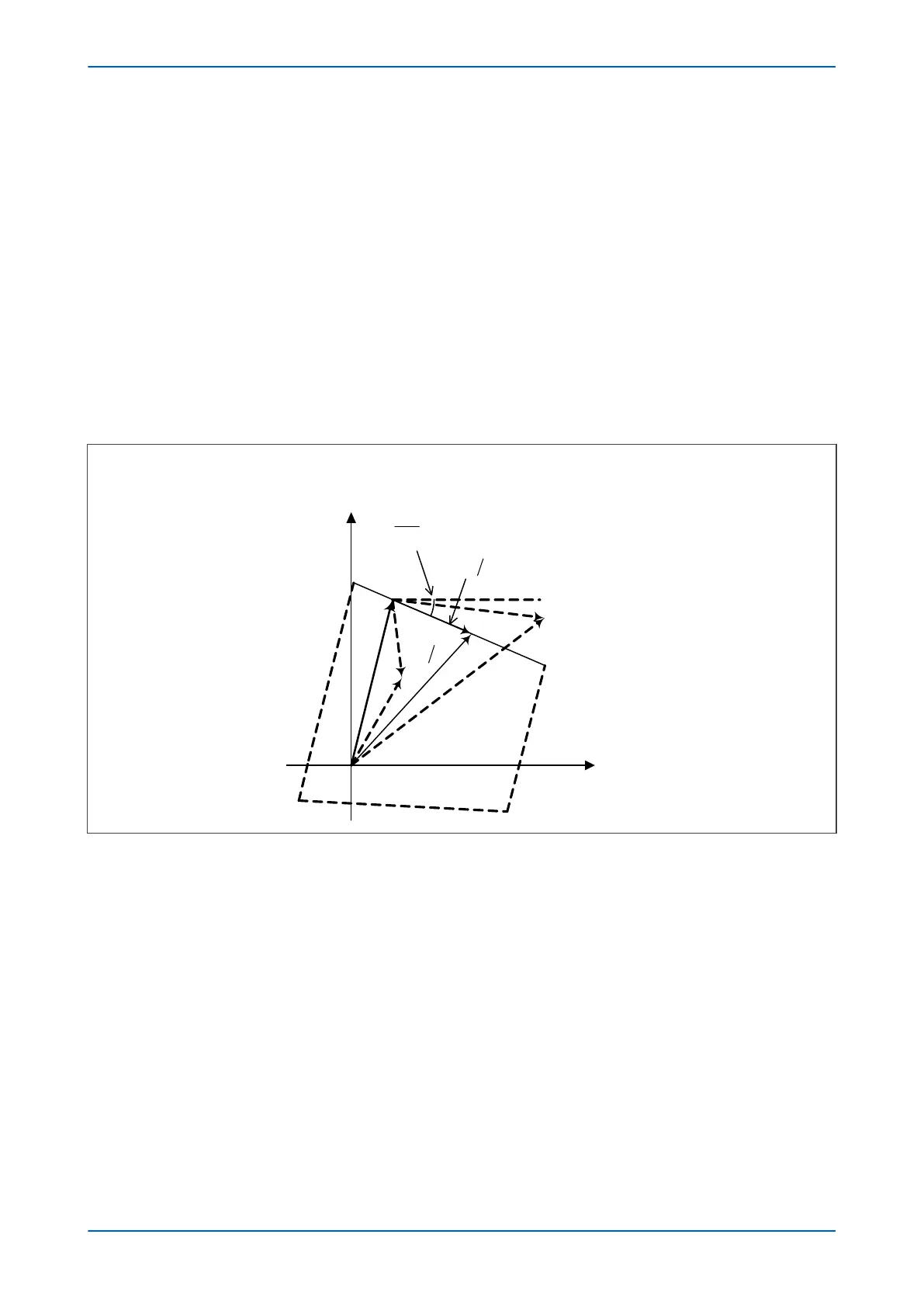
The Impedance Reach line of the characteristic in the Z1 plane is shown in the following diagram:
Figure 65: Impedance Reach line in Z1 plane
For all V/I vectors below the Impedance Reach line, the following condition is true:
Ð
(V/I-Z) ≤ σ
or
Ð
(V – I.Z) ≤ I + σ
If mutual compensation is not applied, for an earth-fault loop
V = Vph
and
I = Iph + k
ZN
.IN
so the signals fed into comparator are:
S1 = Vph – Iph.Z
replica
Chapter 7 - Distance Protection P543i/P545i
156 P54x1i-TM-EN-1

 Loading...


