remain stable for magnetising inrush conditions, but to operate for internal faults. To discriminate between the
two, an unrestrained high set differential protection is included. If Inrush Restraint is set either to Restraint or
to Blocking, an unrestrained high set differential protection becomes visible. It is provided to ensure rapid
clearance for heavy internal faults with saturated CTs. The element can be enabled or disabled according to the
HighSet Status setting in the CURRENT DIFF column. The pick-up value can be set between 4 In and 32 In (RMS
values) using the Id High Set cell.
Note:
The Id High Set cell should be set so that it is in excess of the anticipated inrush current after ratio correction has been
applied.
10.4
OVERFLUXING RESTRAINT
Sometimes the protected transformer is subject to overfluxing due to temporary overloading with a voltage in
excess of the nominal voltage, or a reduced voltage frequency. For example, when a load is suddenly
disconnected from a power transformer, the voltage at the input terminals of the transformer may rise by 10-20%
of the rated value. Since the voltage increases, the flux also increases. As a result, the transformer steady state
excitation current becomes higher. The resulting excitation current flows in one winding only and therefore
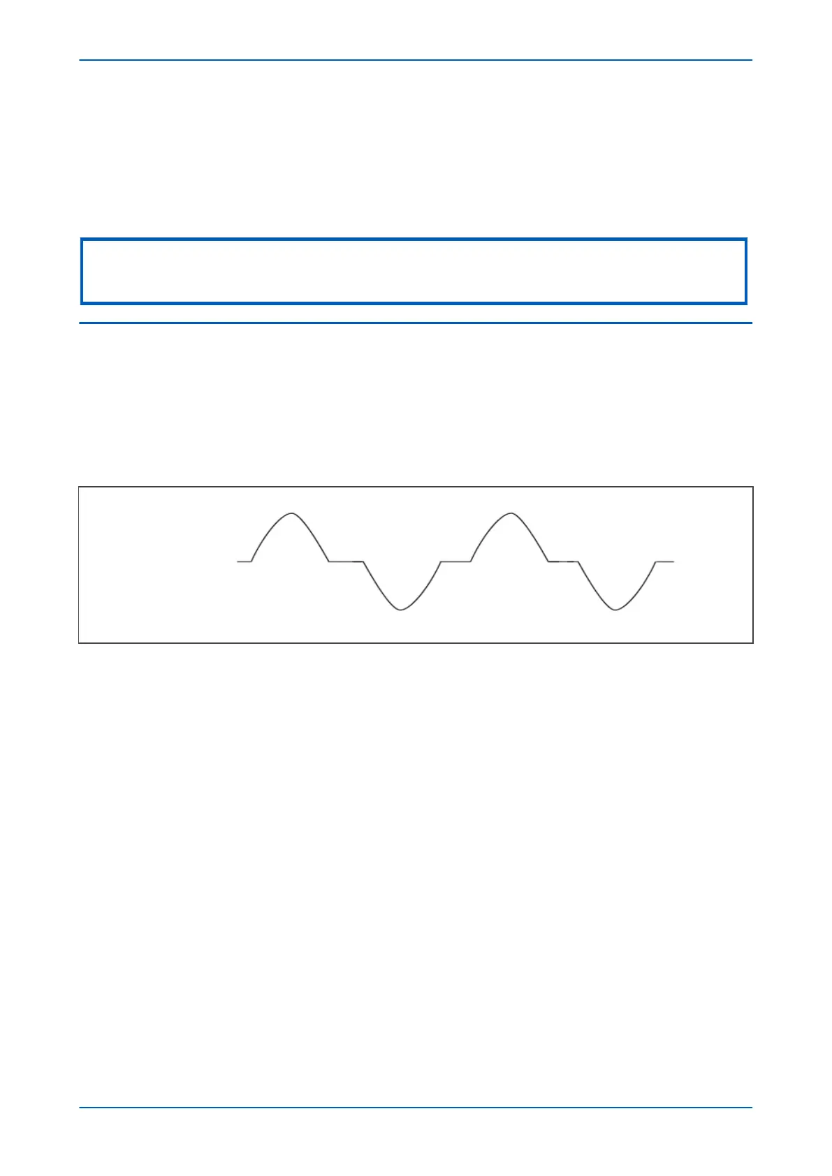
appears as differential current which may rise to a value high enough to operate the differential protection. A
typical differential current waveform during such a condition is as follows.
Figure 42: Typical overflux current waveform
Such waveforms have a significant 5th harmonic content. We can therefore develop a restraining method based
on the 5th harmonic content of the inrush current. The mechanism by which this is achieved, is called fifth
harmonic blocking.
10.4.1
FIFTH HARMONIC BLOCKING
A characteristic of overfluxing is that there is a strong fifth harmonic component associated.
When applied to the protection of transformer feeders, this product measures the fifth harmonic components of
the input currents to detect overfluxing. This detection can be used to block operation of the current differential
protection.
If the 5th Harmonic setting is enabled, then the operation of the current differential elements will be blocked if
overfluxing is detected.
Overfluxing blocking is implemented on a phase-by-phase basis. Blocking is prevented if the phase current is less
than 5% In. If the phase current exceeds 5% In, and the element is enabled, then if the ratio of fifth harmonic
current to the fundamental component exceeds the the Ih(5) %> setting, operation of the current differential is
blocked on that phase. Blocking of affected phases is applied both at local and at remote terminals.
You can choose whether to block just the affected phase, or to block all three phases using the Ih(5) CrossBlock
cell. If you disable Ih(5) CrossBlock, only the affected phase is blocked. If you enable Ih(5) CrossBlock, all phases
are blocked.
P543i/P545i Chapter 6 - Current Differential Protection
P54x1i-TM-EN-1 119

 Loading...


