A user settable time delay (TOC Delay) starts when the CB opens, after which TOR is enabled. The time delay must
not exceed the minimum Dead Time setting of the auto-reclose because both times start simultaneously and TOR
protection must be ready by the time the CB closes on potentially persistent faults.
While the Trip on Reclose Mode is active, the protection trips instantaneously for pick up of any selected Distance
zone. You select the zone with the TOR Tripping setting. For example, Zone 2 could operate without waiting for the
usual time delay if a fault is in Zone 2 on CB closure. Also Current No Volts can be mapped for fast fault clearance
on line reclosure on a permanent fault. To operate for faults on the entire circuit length, at least Zone 1 and Zone 2
should be selected. If no elements are selected, the normal time delayed elements and aided scheme provide the
protection. TOR tripping is three-phase and auto-reclose is blocked.
4.2.1 TRIP ON RECLOSE MODE
To ensure fast isolation of all persistent faults following the circuit breaker reclosure, enable this feature with
appropriate zones selected or Current No Volt (CNV) level detectors.
● TOC Delay: The Trip on Reclose (TOR) is activated after TOC Delay has expired. The setting must not exceed
the minimum autoreclose Dead Time setting to make sure that the TOR is active immediately on reclose
command.
● TOC Reset Delay: We recommend 500ms as a typical setting.
4.2.2
TOR TRIPPING LOGIC FOR APPROPRIATE ZONES
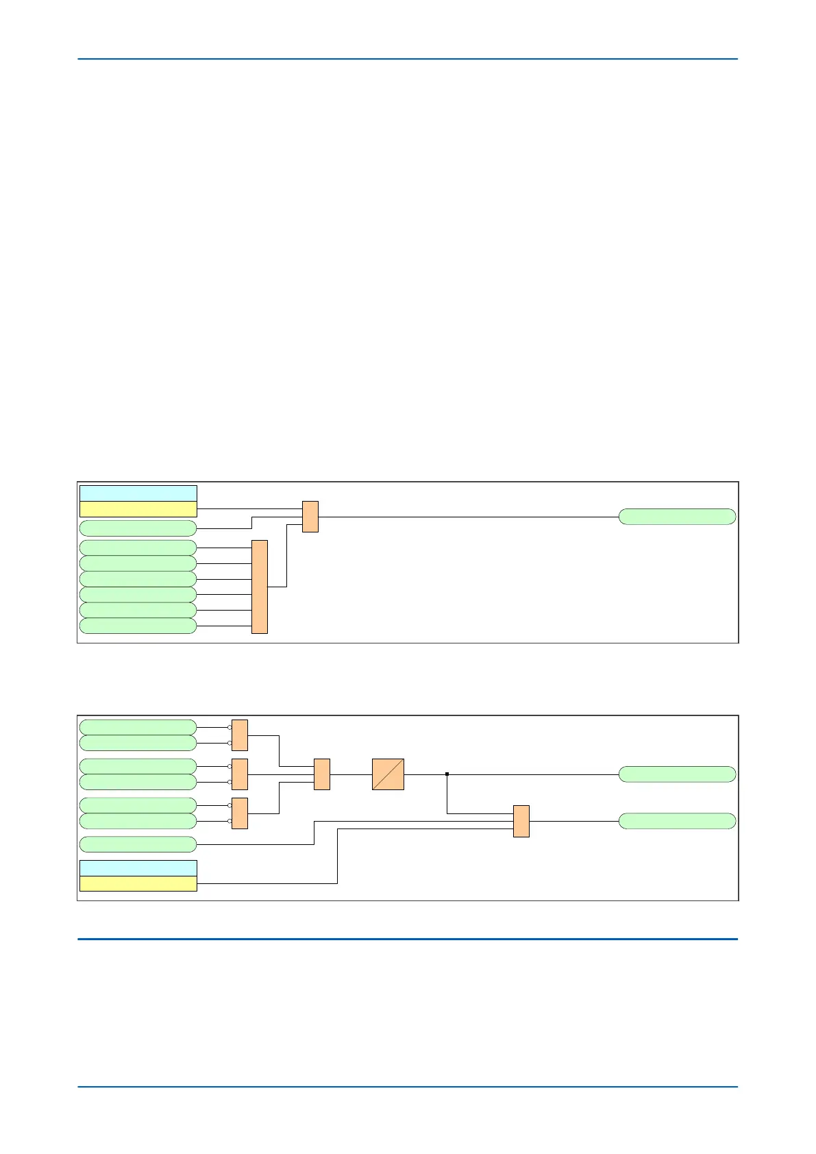
V02755
TOR Tripping
Zone 1
TOR Active
&
Zone1 AN Element
Zone1 BN Element
Zone1 CN Element
Zone1 AB Element
Zone1 BC Element
Zone1 CA Element
1
TOR Trip Zone 1
Note: This diagram shows Zone 1 only. The other zones follow the same
principles.
878
960
961
962
963
964
965
704
Figure 142: TOR Tripping logic for appropriate zones
4.2.3
TOR TRIPPING LOGIC WITH CNV
V02757
Fast OV PHA
CNV ACTIVE
&
1&
&
20 ms
0
IA< Start
Fast OV PHB
Fast OV PHC
IB< Start
IC< Start
TOR Tripping
Current No Volts
TOR Active
TOR Trip CNV
&
559
864
560
865
561
866
878
556
557
Figure 143: TOR Tripping logic with CNV
4.3
POLARISATION DURING CIRCUIT ENGERGISATION
While the Switch on to Fault (SOTF) and Trip on Reclose (TOR) modes are active, the directionalised distance
elements are partially cross polarised from other phases. The same proportion of healthy phase to faulted phase
voltage, as given by the Distance Polarizing setting in the DISTANCE SETUP menu, is used.
Chapter 9 - Non-Aided Schemes P543i/P545i
262 P54x1i-TM-EN-1

 Loading...


