E00801
IED
E
S F
Z
S
Z
L
Z
E
V
A
- G
V
A
- G
S
G,F
V
B
- G
V
B
- G
V
B
- G
V
C
- G
V
C
- G
V
C
- G
G,F
G,F
R
V
C
- G
V
C
- G
V
C
- G
V
B
- G
V
B
- G
V
B
- G
V
RES
V
RES
V
RES
V
RES
=
Z
S0
+ 3
ZE
2Z
S1
+ Z
S0
+ 2Z
L1
+ Z
L0
+ 3Z
E
X 3 E
V
A
- G
V
A
- G
N
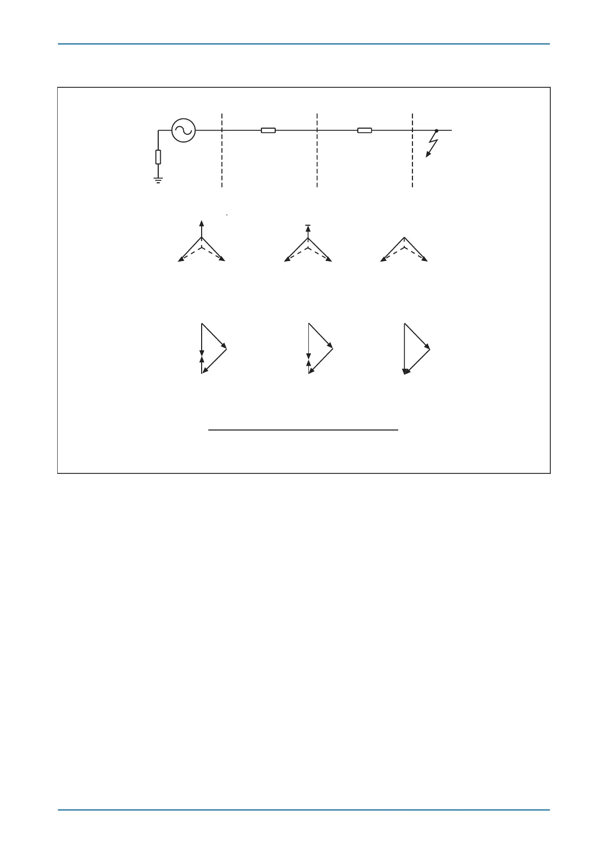
Figure 236: Residual voltage for an impedance earthed system
An impedance earthed system will always generate a relatively large degree of residual voltage, as the zero
sequence source impedance now includes the earthing impedance. It follows then that the residual voltage
generated by an earth fault on an insulated system will be the highest possible value (3 x phase-neutral voltage),
as the zero sequence source impedance is infinite.
5.3.3
SETTING GUIDELINES
The voltage setting applied to the elements is dependent on the magnitude of residual voltage that is expected to
occur during the earth fault condition. This in turn is dependent on the method of system earthing employed.
Also, you must ensure that the protection setting is set above any standing level of residual voltage that is present
on the system.
Chapter 14 - Voltage Protection Functions P543i/P545i
408 P54x1i-TM-EN-1

 Loading...


