IGNITION SYSTEM
Avoid touching
the
spark plug
and
tester probes
to
prevent electric
shock.
With the ignition coil primary wire connected, con-
nect the peak voltage adapter or tester probes to the
ignition
coil.
TOOLS:
Peak voltage tester (U.S.A. only)
or
Peak voltage adaptor 07HGJ-0020100
(not available
in
U.S.A.)
with commercially available digital multimeter
(impedance
10
M Q /D C V minimum)
or
IgnitionMate
peak voltage tester, MTP-08-0193 (U.S.A. only)
CONNECTION:
Black/yellow
(+) -
Body ground
(-)
Turn the ignition switch to ON and the engine stop
switch to "o".
Crank the engine with the kickstarter and measure
the ignition coil primary peak voltage.
PEAK VOLTAGE:
80 V
minimum
If the peak voltage is lower than specified value, fo l-
low the checks described in the troubleshooting
chart (page 16-4).
Install the removed parts in the reverse order of
removal.
IGNITION PULSE GENERATOR PEAK
VOLTAGE
NOTE:
•
Check cylinder compression and make sure the
spark plug is installed correctly.
Remove the body cover (page 2-7).
Turn the ignition switch to OFF.
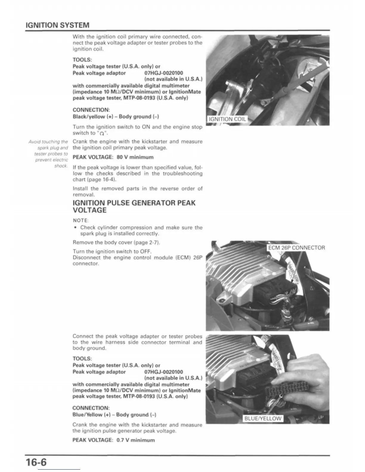
Disconnect the engine control module (ECM) 26P
connector.
ECM 26P CONNECTOR
Connect the peak voltage adapter or tester probes
to the wire harness side connector terminal and
body ground.
TOOLS:
Peak voltage tester (U.S.A. only)
or
Peak voltage adaptor 07HGJ-0020100
(not available
in
U.S.A.
with commercially available digital multimeter
(impedance
10
MS2/DCV minimum)
or
IgnitionMate
peak voltage tester, MTP-08-0193 (U.S.A. only)
CONNECTION:
Blue/Yellow
(+) -
Body ground
(-)
Crank the engine with the kickstarter and measure
the ignition pulse generator peak voltage.
PEAK VOLTAGE:
0.7 V
minimum
16-6

 Loading...