EasyManua.ls Logo

Honda Metropolitan CHF50 User Manual

Honda Metropolitan CHF50
319 pages
To Next Page IconTo Next Page
To Previous Page IconTo Previous Page
Page #3 background imageLoading...
Page #3 background image
HOW TO USE THIS MANUAL
This service manual describes the service procedures for the CHF50.
Follow the Maintenance Schedule (Section 3) recommendations to
ensure that the vehicle is in peak operating condition and the emission
levels are within the standard set by the California Air Resources
Board (CARB).
Performing the first scheduled maintenance is very important. It
compensates for the initial wear that occurs during the break-in
period.
Sections 1 and 3 apply to the whole motorcycle. Section 2 illustrates
procedures for removal/installation of components that may be
required to perform service described in the following sections.
Section 4 through 18 describe parts of the motorcycle, grouped
according to location.
Find the section you want on this page, then turn to the table of
contents on the first page of the section.
Most sections start with an assembly or system illustration, service
information and troubleshooting for the section. The subsequent
pages give detailed procedure.
If you are not familiar with this motorcycle, read Technical Feature in
Section 20.
If you don't know the source of the trouble, go to section 21
Trou bl esho o ting .
Yo u r s af et y, a n d t h e s a fe t y o f o t he r s, i s v er y i m p o r t a n t. To h e l p
you make informed decisions we have provided safety
messages and other information throughout this manual. Of
course, it is not practical or possible to warn you about all the
hazards associated with servicing this vehicle.
Yo u mu s t u s e y ou r o w n g o o d j u d ge m en t .
Yo u w i l l f i n d i m p o r t a n t s a fe t y i n fo r m a t i on i n a v ar i e t y o f f o r m s
including:
•Safety Labels on the vehicle
•Safety Messages preceded by a safety alert symbol and
one of three signal words, DANGER, WARNING, or CAU-
TION.
These signal words mean:
You WILL be KILLED or SERIOUSLY
HURT if you don’t follow instructions.
You C A N b e K I L LED o r SE R I O U SLY
HURT if you don’t follow instructions.
You CAN be HURT if yo u do n t f o l l ow
instructions.
•Instructions how to service this vehicle correctly and safely.
As you read this manual, you will find information that is preceded by a
symbol. The purpose of this message is to help prevent
damage to your vehicle, other property, or the environment.
ALL INFORMATION, ILLUSTRATIONS, DIREC-
TIONS AND SPECIFICATIONS INCLUDED IN
THIS PUBLICATION ARE BASED ON THE
LATEST PRODUCT INFORMATION AVAIL-
ABLE AT THE TIME OF APPROVAL FOR
PRINTING. HONDA MOTOR CO., LTD.
RESERVES THE RIGHT TO MAKE CHANGES
AT ANY TIM E WITHO UT N OT ICE AN D WI TH-
OUT INCURRING ANY OBLIGATION WHATSO-
EVER. NO PART OF THIS PUBLICATION MAY
BE REPRODUCED WITHOUT WRITTEN PER-
MISSION. THIS MANUAL IS WRITTEN FOR
PERSONS WHO HAVE ACQUIRED BASIC
KNOWLEDGE OF MAINTENANCE ON HONDA
MOTORCYCLES, MOTOR SCOOTERS OR
ATV S.
Honda Motor Co., Ltd.
SERVICE PUBLICATION OFFICE
CONTENTS
GENERAL INFORMATION
FRAME/BODY PANELS/EXHAUST
SYSTEM
MAINTENANCE
LUBRICATION SYSTEM
FUEL SYSTEM
ENGINE AND DRIVE TRAIN
COOLING SYSTEM
ENGINE REMOVAL/INSTALLATION
CYLINDER HEAD/VALVES
KICKSTARTER/DRIVE PULLEY/
DRIVEN PULLEY/CLUTCH
FINAL REDUCTION
ALTERNATOR/STARTER
CRANKSHAFT/PISTON/CYLINDER
FRONT WHEEL/BRAKE/
SUSPENSION/STEERING
REAR WHEEL/BRAKE/SUSPENSION
BATTERY/CHARGING SYSTEM
IGNITION SYSTEM
ELECTRIC STARTER
LIGHTS/METERS/SWITCHES
WIRING DIAGRAMS
TECHNICAL FEATURE
TROUBLESHOOTING
CHASSIS
ELECTRICAL
22
21
20
19
18
17
16
15
14
13
12
11
10
9
8
7
6
5
4
2
3
1
INDEX
Date of Issue: July, 2007
©Honda Motor Co., Ltd.

Table of Contents

Question and Answer IconNeed help?

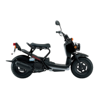
Do you have a question about the Honda Metropolitan CHF50 and is the answer not in the manual?

Honda Metropolitan CHF50 Specifications

General IconGeneral
Engine Type49cc liquid-cooled single-cylinder four-stroke
IgnitionCDI
TransmissionAutomatic V-Matic belt drive
Rear SuspensionSingle shock
Front BrakeDrum
Rear BrakeDrum
Front Tire80/100-10
Rear Tire80/100-10
Seat Height28.3 inches
Fuel Capacity1.3 gallons
Bore x Stroke37.8mm x 44.0mm
Compression Ratio12.0:1
StarterElectric
Curb Weight179 pounds

Summary

1. GENERAL INFORMATION

Service Rules

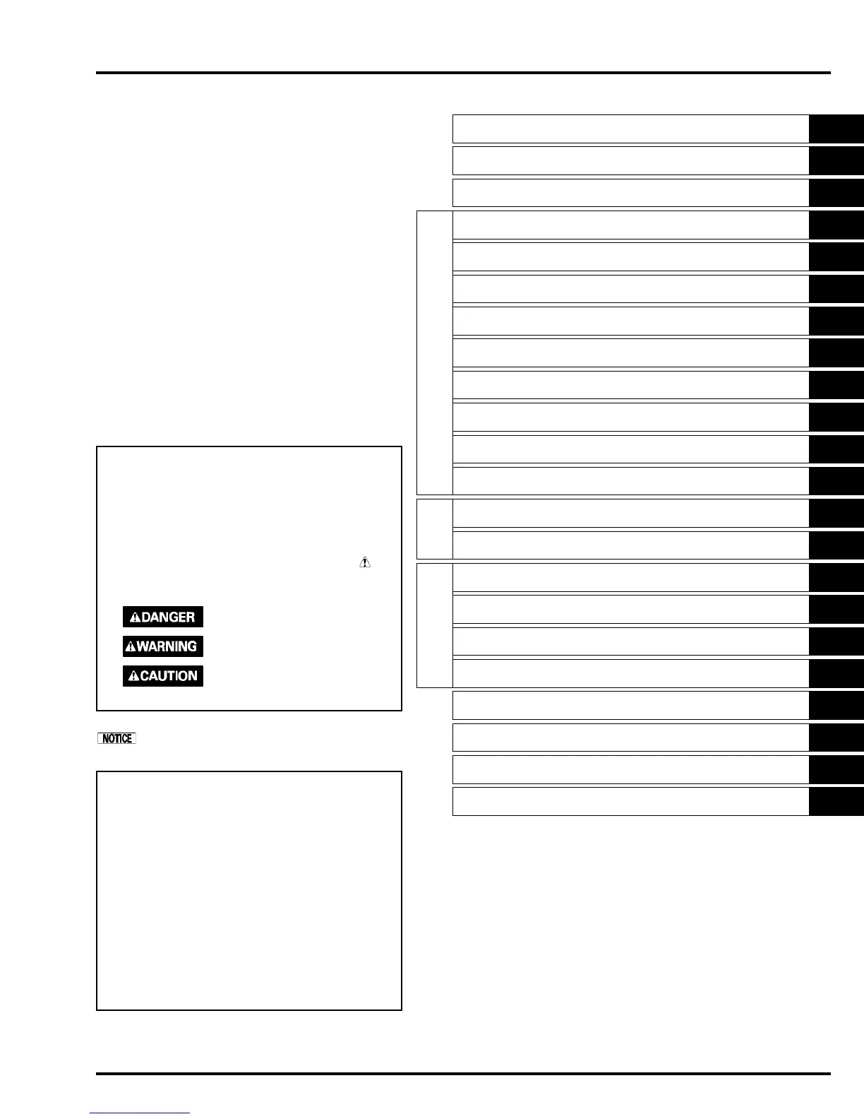
Basic guidelines for performing service and repairs on the scooter.

General Specifications

Key technical data, dimensions, and capacities of the vehicle.

Standard Torque Values

General torque specifications for common fasteners.

Engine & Frame Torque Values

Specific torque values for engine and frame mounting points.

3. MAINTENANCE

Maintenance Schedule

Recommended service intervals for various vehicle components.

Valve Clearance

Procedure for inspecting and adjusting valve clearance.

Engine Oil

Procedure for checking the engine oil level.

Brake System

Adjustment of brake lever free play.

4. LUBRICATION SYSTEM

Oil Pump

Procedure for removing, disassembling, inspecting, and assembling the oil pump.

5. FUEL SYSTEM

Carburetor Disassembly

Procedure for disassembling the carburetor into its components.

Carburetor Assembly

Procedure for reassembling the carburetor.

Pilot Screw Adjustment: ('02 - '05 model)

Procedure for adjusting the pilot screw on '02-'05 models.

Pilot Screw Adjustment: (After '05 model)

Procedure for adjusting the pilot screw on models after '05.

6. COOLING SYSTEM

Coolant Replacement

Preparation and procedure for replacing engine coolant.

Replacement/Air Bleeding

Coolant replacement and air bleeding procedures.

Water Pump/Thermostat

Removal, inspection, and installation of the water pump and thermostat.

7. ENGINE REMOVAL/INSTALLATION

Engine Removal

Step-by-step procedure for removing the engine from the frame.

Engine Installation

Step-by-step procedure for installing the engine into the frame.

8. CYLINDER HEAD/VALVES

Cylinder Compression Test

Procedure for testing engine cylinder compression.

Camshaft/Rocker Arm Removal

Procedure for removing the camshaft and rocker arms.

Valve Guide Replacement

Procedure for replacing valve guides.

Cylinder Head Disassembly

Steps for disassembling the cylinder head.

Valve Seat Inspection/Refacing

Procedure for inspecting and refacing valve seats.

Cylinder Head Assembly

Procedure for assembling the cylinder head with valves.

Cylinder Head Installation

Procedure for installing the cylinder head onto the engine.

Camshaft/Rocker Arm Installation

Procedure for installing the camshaft and rocker arms.

9. KICKSTARTER/DRIVE PULLEY/DRIVEN PULLEY/CLUTCH

Kick starter Disassembly

Steps for disassembling the kickstarter mechanism.

Kick starter Assembly

Procedure for assembling the kickstarter mechanism.

Drive Pulley Removal

Steps for removing the drive pulley assembly.

Inspection

Inspection of drive belt, weight rollers, and pulley faces.

Assembly

Procedure for assembling the drive pulley components.

Clutch/Driven Pulley Removal

Steps for removing the clutch and driven pulley.

Clutch/Driven Pulley Disassembly

Procedure for disassembling the clutch and driven pulley.

10. FINAL REDUCTION

Final Reduction Disassembly Transmission Disassembly

Steps for disassembling the transmission case.

Driveshaft Removal

Procedure for removing the driveshaft.

Final Reduction Assembly

Procedure for assembling the final reduction unit.

11. ALTERNATOR/STARTER

Alternator/Starter Removal

Steps for removing the alternator/starter assembly.

Installation

Steps for installing the alternator/starter assembly.

12. CRANKSHAFT/PISTON/CYLINDER

Specifications

Detailed specifications for crankshaft, piston, cylinder, and connecting rod.

Crankcase Separation

Procedure for separating the crankcase halves.

Crankshaft/Piston Crankshaft Removal

Steps for removing the crankshaft and piston.

Piston Removal

Procedure for removing piston rings and piston pin.

Crankshaft Inspection

Inspection of connecting rod big end side clearance and crankshaft runout.

Piston/Cylinder Inspection

Inspection of piston rings, cylinder bore, and piston pin.

Piston Installation

Procedure for installing piston rings and piston.

Crankshaft Installation

Procedure for installing the crankshaft and crankcase.

Crankcase Assembly

Procedure for assembling the crankcase.

13. FRONT WHEEL/BRAKE/SUSPENSION/STEERING

Wheel Bearing

Inspection and replacement of wheel bearings.

Fork Removal

Steps for removing the front fork tubes.

Bearing Replacement

Procedure for replacing steering stem bearings.

Installation

Procedure for installing the steering stem assembly.

14. REAR WHEEL/BRAKE/SUSPENSION

Torque Values

Torque specifications for rear end fasteners.

Troubleshooting

Common problems related to rear wheel, suspension, and brakes.

Installation

Procedure for installing the rear shock absorber.

15. BATTERY/CHARGING SYSTEM

Battery Removal/Installation

Procedure for removing and installing the battery.

16. IGNITION SYSTEM

17. ELECTRIC STARTER

Troubleshooting

Troubleshooting steps when the starter does not operate.

18. LIGHTS/METERS/SWITCHES

19. WIRING DIAGRAMS

Standard ('02 - '05 model)

Wiring diagram for standard '02-'05 models.

P-type ('02 - '05 model)

Wiring diagram for P-type '02-'05 models.

After '05 model

Wiring diagram for models after '05.

21. TROUBLESHOOTING

Engine Does Not Start or Is Hard to Start

Troubleshooting steps for starting problems.

Engine Lacks Power

Troubleshooting steps for engine power loss.

Poor Performance at Low and Idle Speed

Troubleshooting steps for low-speed and idle performance issues.

Poor Performance at High Speed

Troubleshooting steps for high-speed performance issues.

Poor Handling

Troubleshooting steps for handling and stability problems.

Related product manuals