IGNITION SYSTEM
16-8
IGNITION TIMING
• The ignition timing is factory preset and need
only be checked when an electrical system com-
ponent is replaced.
Warm up the engine to normal operating tempera-
ture.
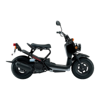
Stop the engine and remove the radiator cover
(page 6-5) and plug maintenance lid.
Connect the timing light to the spark plug wire.
Start the engine, let it idle and check the ignition
timing.
The ignition timing is correct if the "F" mark on the
flywheel aligns with the index mark at idle.
Install the removed parts in the reverse order of
removal.
THROTTLE POSITION SENSOR
SYSTEM INSPECTION
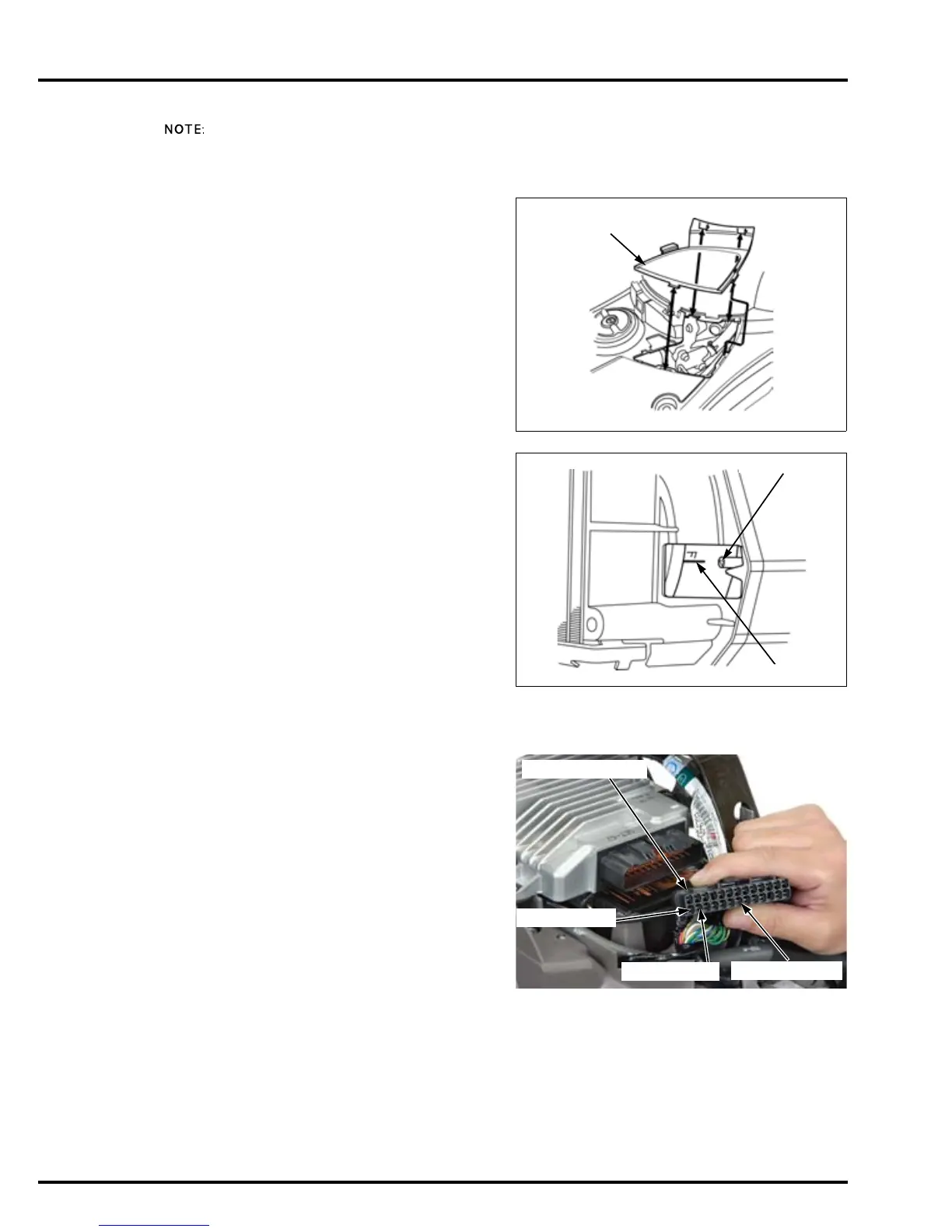
Disconnect the ECM 26P connector.
Measure the resistance between the Yellow/red and
Blue/green wire terminals.
Measure the resistance between the Yellow/blue
and Blue/green wire terminals at the wire harness
side connector with the throttle operation.
Read the
instructions for
timing light
operation.
STANDARD: 4 – 6 kΩ (20°C/68°F)
Full open – Full closed position:
Resistance decrease
Full closed – Full open position:
Resistance increase
26P CONNECTOR
BLUE/GREEN
YELLOW/RED
YELLOW/BLUE

 Loading...