TESTING AND ADJUSTING
TABLE OF JUDGMENT STANDARD VALUES
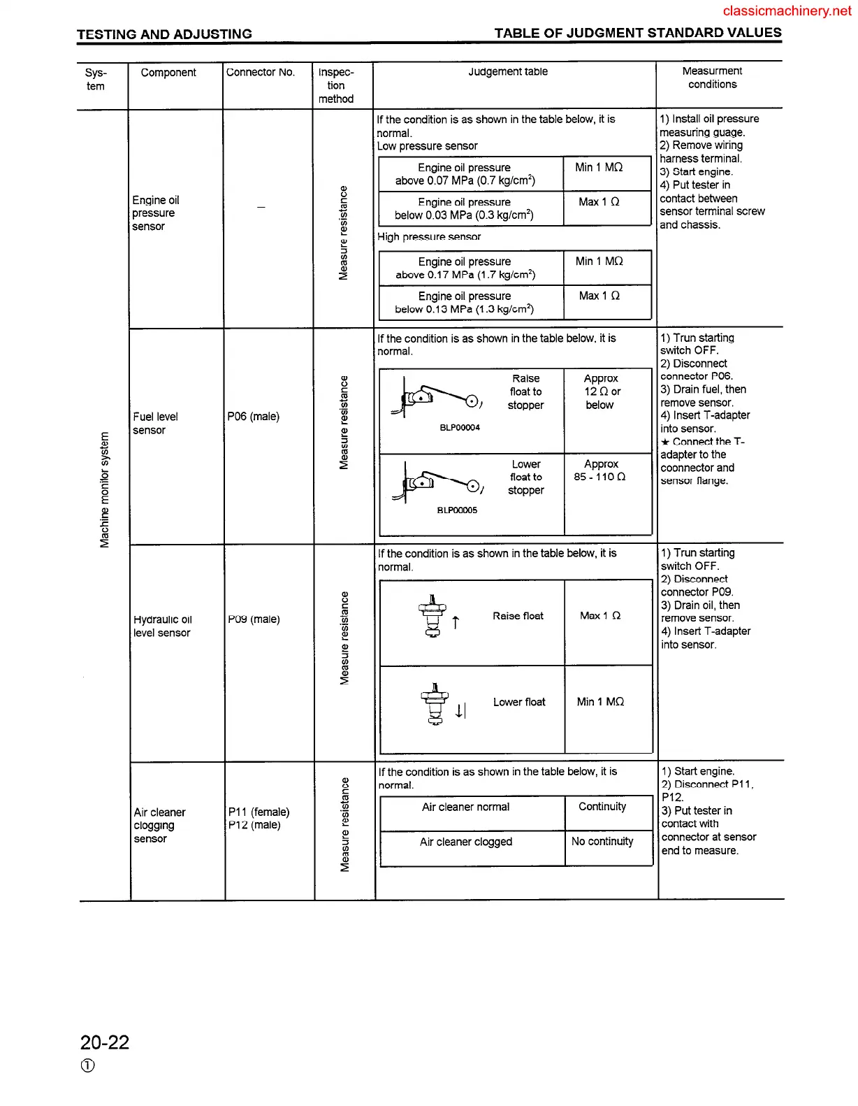
sys-
tem
Component
Engine oil
xessure
sensor
Fuel level
sensor
Hydraulic oil
level sensor
Air cleaner
clogging
sensor
ionnector No.
_
‘06 (male)
‘09 (male)
VI (female)
‘12 (male)
nspec-
tion
nethod
Judgement table
f the condition is as shown in the table below, it is
iormal.
Low pressure sensor
11
High pressure sensor
If the condition is as shown in the table below, it is
normal.
the condition is as shown in the table below, it is
xmal.
I I
Raisefloat 1 Maxi C? ~ $ r
Lower float Min 1 MD
the condition is as shown in the table below, it is
ormal.
Air cleaner normal
I
Continuity
Air cleaner clogged
No continuity
Measurment
conditions
I) Install oil pressure
neasuring guage.
?) Remove wiring
larness terminal.
3) Start engine.
1) Put tester in
:ontact between
sensor terminal screw
2nd chassis.
I) Trun starting
switch OFF.
2) Disconnect
:onnector P06.
3) Drain fuel, then
‘emove sensor.
1) Insert T-adapter
nto sensor.
k Connect the T-
adapter to the
:oonnector and
sensor flange.
I) Trun starting
switch OFF.
2) Disconnect
:onnector PO9.
3) Drain oil, then
‘emove sensor.
4) Insert T-adapter
nto sensor.
1) Start engine.
2) Disconnect PI 1,
P12.
3) Put tester in
contact with
connector at sensor
end to measure.
20-22
0
 Loading...


