TROUBLESHOOTING
EXPLANATION OF CONTROL MECHANISM FOR ELECTRICAL SYSTEM
EXPLANATION OF CONTROL MECHANISM FOR ELECTRICAL SYSTEM
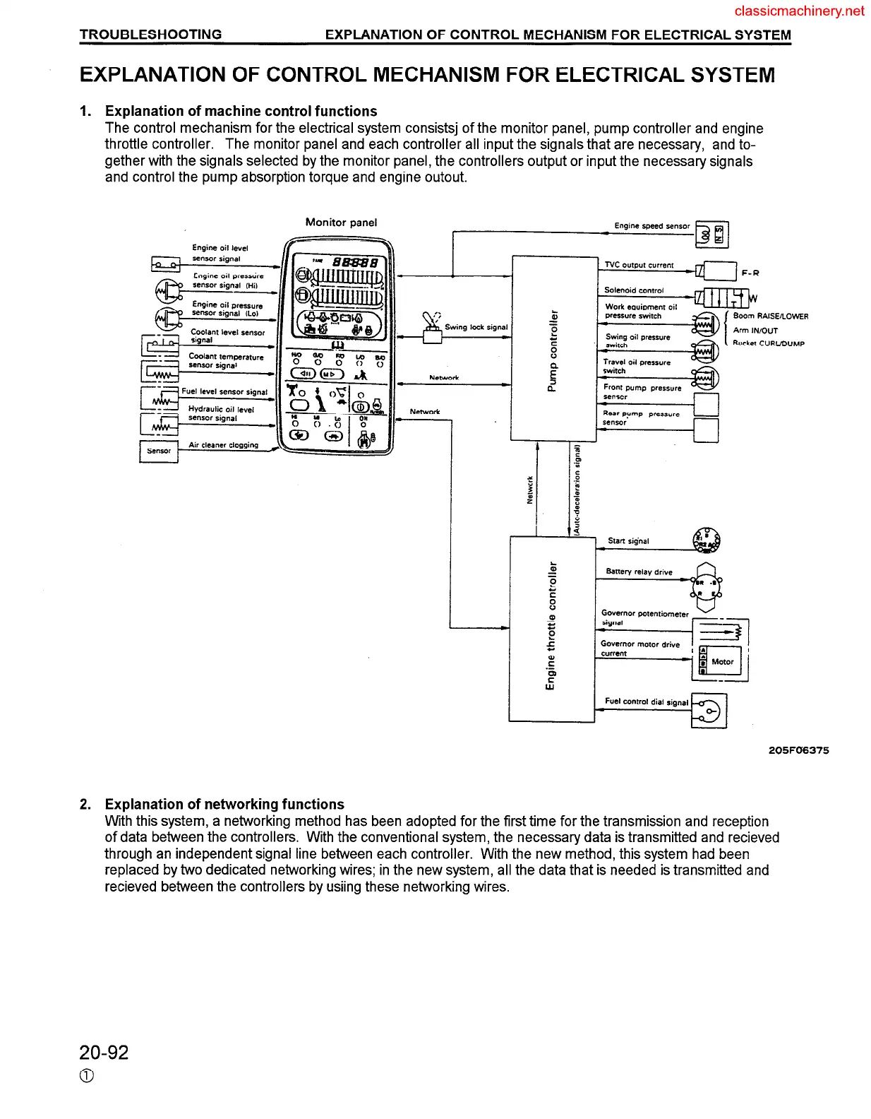
1. Explanation of machine control functions
2.
The control mechanism for the electrical system consistsj of the monitor panel, pump controller and engine
throttle controller.
The monitor panel and each controller all input the signals that are necessary, and to-
gether with the signals selected by the monitor panel, the controllers output or input the necessary signals
and control the pump absorption torque and engine outout.
Monitor panel
Engine speed sensor
N.%WOrt
lock signal
i
E”
z
m RAISE
IN/OUT
ret CURL
i/l
A
.OWER
>UMP
Explanation of networking functions
With this system, a networking method has been adopted for the first time for the transmission and reception
of data between the controllers. With the conventional system, the necessary data is transmitted and recieved
through an independent signal line between each controller. With the new method, this system had been
replaced by two dedicated networking wires; in the new system, all the data that is needed is transmitted and
recieved between the controllers by usiing these networking wires.
20-92
0
 Loading...