DISASSEMBLY AND ASSEMBLY
WORK EQUIPMENT
REMOVAL OF WORK
EQUIPMENT ASSEMBLY
A
Extend the arm and bucket fully, lower the work
equipment to the ground, and set the safety lock
lever to the LOCK position.
1.
2.
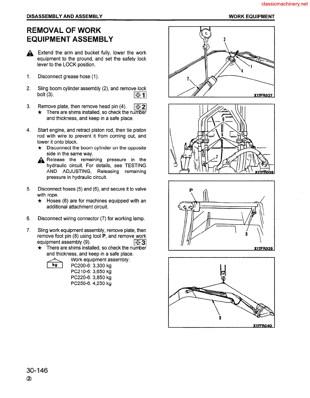
Disconnect grease hose (1).
Sling boom cylinder assembly (2), and remove lock
bolt (3).
mj
3.
Remove plate, then remove head pin (4).
m
* There are shims installed, so check the number
and thickness, and keep in a safe place.
4. Start engine, and retract piston rod, then tie piston
rod with wire to prevent it from coming out, and
lower it onto block.
*
A
Disconnect the boom cylinder on the opposite
side in the same way.
Release the remaining pressure in the
hydraulic circuit. For details, see TESTING
AND ADJUSTING, Releasing remaining
pressure in hydraulic circuit.
5. Disconnect hoses (5) and (6) and secure it to valve
with rope.
* Hoses (6) are for machines equipped with an
additional attachment circuit.
6.
Disconnect wiring connector (7) for working lamp.
7. Sling work equipment assembly, remove plate, then
remove foot pin (8) using tool P, and remove work
equipment assembly (9).
j, There are shims installed, so check the
and thickness, and keep in a safe place.
Work equipment assembly:
PC200-6: 3,300 kg
PC210-6: 3,650 kg
PC220-6: 3,850 kg
PC250-6: 4,250 kg
30-146
0
 Loading...


