DISASSEMBLY AND ASSEMBLY
CONTROL PUMP
REMOVAL OF CONTROL PUMP
ASSEMBLY
A
0
1.
2.
3.
Lower the work equipment completely to the ground
and stop the engine. Then loosen the oil filler cap
slowly to release the pressure inside the hydraulic
tank.
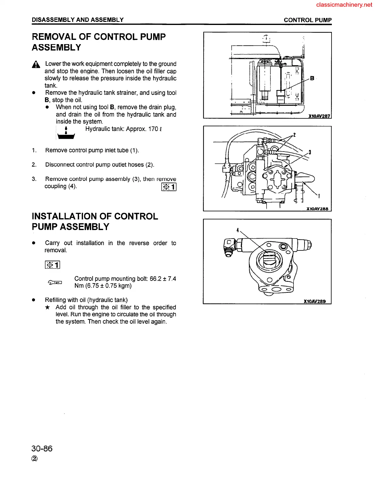
Remove the hydraulic tank strainer, and using tool
B, stop the oil.
l When not using tool B, remove the drain plug,
and drain the oil from the hydraulic tank and
inside the system.
Hydraulic tank: Approx. 170 e
Remove control pump inlet tube (1).
Disconnect control pump outlet hoses (2).
Remove control pump assembly (3) then remove
coupling (4).
m
INSTALLATION OF CONTROL
PUMP ASSEMBLY
0
Carry out installation in the reverse order to
removal.
Control pump mounting bolt: 66.2 r 7.4
Nm (6.75 f 0.75 kgm)
r----
l
Refilling with oil (hydraulic tank)
j, Add oil through the oil filler to the specified
level. Run the engine to circulate the oil through
the system. Then check the oil level again.
30-86
0
 Loading...


