DISASSEMBLY AND ASSEMBLY FINAL DRIVE
REMOVAL OF FINAL DRIVE
ASSEMBLY
1.
a
2.
3.
Remove sprocket. For details, see REMOVAL OF
SPROCKET.
Lower the work equipment completely to the g
round and stop the engine. Then loosen the oil filler
cap slowly to release the pressure inside the
hydraulic tank.
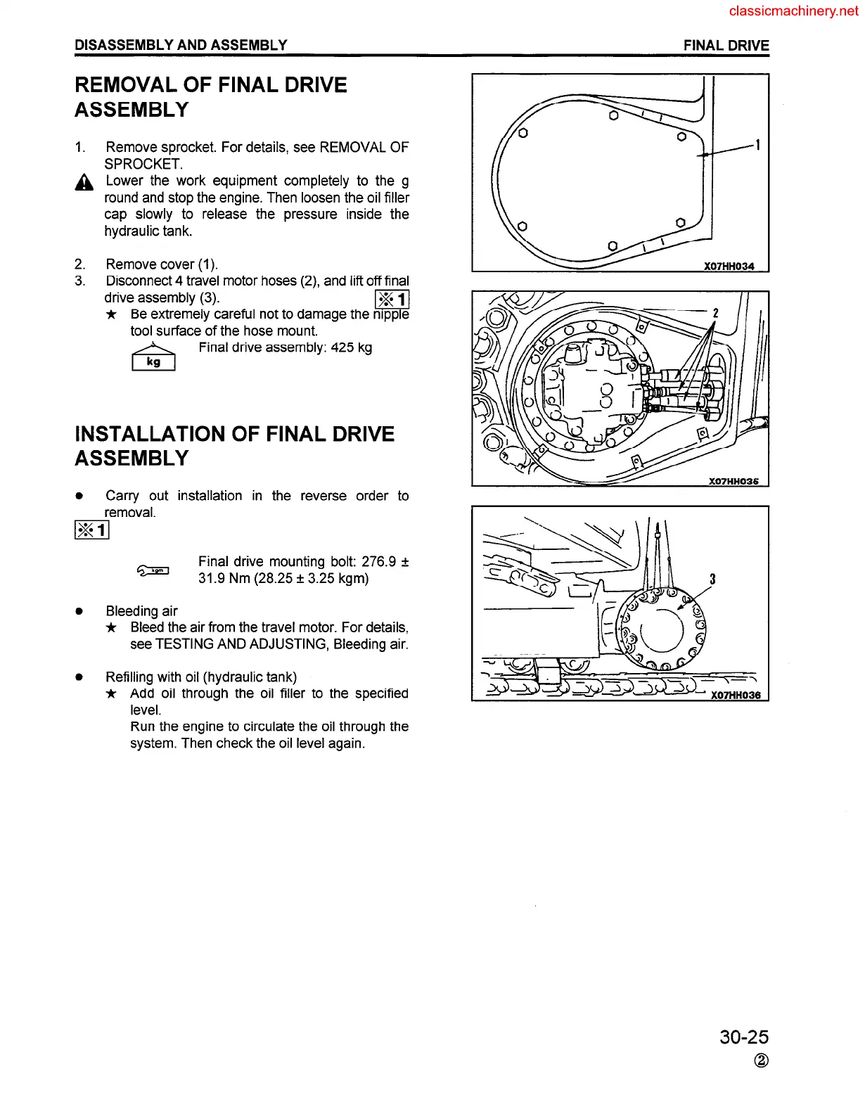
Remove cover (1).
Disconnect 4 travel motor hoses (2) and lift off final
drive assembly (3).
jr Be extremely careful not to damage the
tool surface of the hose mount.
Final drive assembly: 425 kg
INSTALLATION OF FINAL DRIVE
ASSEMBLY
0
Carry out installation in the reverse order to
removal.
m
Final drive mounting bolt: 276.9 f
31.9 Nm (28.25 f 3.25 kgm)
Bleeding air
* Bleed the air from the travel motor. For details,
see TESTING AND ADJUSTING, Bleeding air.
Refilling with oil (hydraulic tank)
* Add oil through the oil filler to the specified
level.
Run the engine to circulate the oil through the
system. Then check the oil level again.
.---I
X07HH034
30-25
0
 Loading...


