DISASSEMBLY AND ASSEMBLY
BOOM CYLINDER
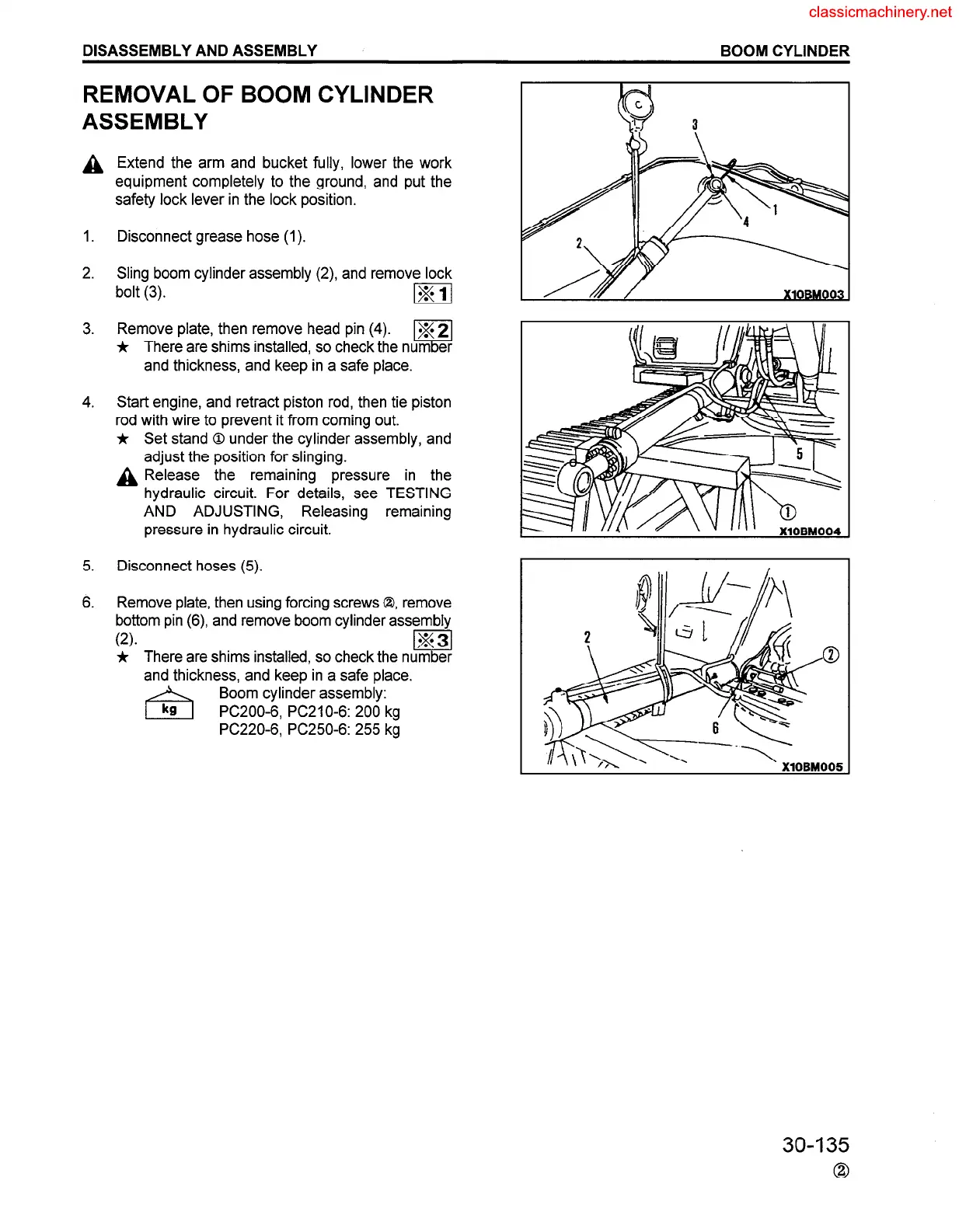
REMOVAL OF BOOM CYLINDER
ASSEMBLY
A
Extend the arm and bucket fully, lower the work
equipment completely to the ground, and put the
safety lock lever in the lock position.
1.
2.
Disconnect grease hose (1).
3.
Sling boom cylinder assembly (2) and remove lock
bolt (3).
m
Remove plate, then remove head pin (4).
*
V
g 2
There are shims installed, so check the num er
and thickness, and keep in a safe place.
4.
Start engine, and retract piston rod, then tie piston
rod with wire to prevent it from coming out.
* Set stand 0 under the cylinder assembly, and
adjust the position for slinging.
A Release the remaining pressure in the
hydraulic circuit. For details, see TESTING
AND ADJUSTING, Releasing remaining
pressure in hydraulic circuit.
5.
Disconnect hoses (5).
6.
Remove plate, then using forcing screws 0, remove
bottom pin (6) and remove boom cylinder assembly
(2).
m
* There are shims installed, so check the number
and thickness, and keep in a safe place.
Boom cylinder assembly:
PC200-6, PC210-6: 200 kg
PC220-6, PC250-6: 255 kg
30-I 35
0
 Loading...


