DISASSEMBLY AND ASSEMBLY
REVOLVING FRAME
REMOVAL OF REVOLVING
FRAME ASSEMBLY
1.
2.
3.
4.
5.
6.
Remove 2 boom cylinder assemblies. For details,
see REMOVAL OF BOOM CYLINDER ASSEMBLY.
Remove work equipment assembly. For details, see
REMOVAL OF WORK EQUIPMENT ASSEMBLY.
Remove counterweight assembly. For details, see
REMOVAL OF COUNTERWEIGHT ASSEMBLY.
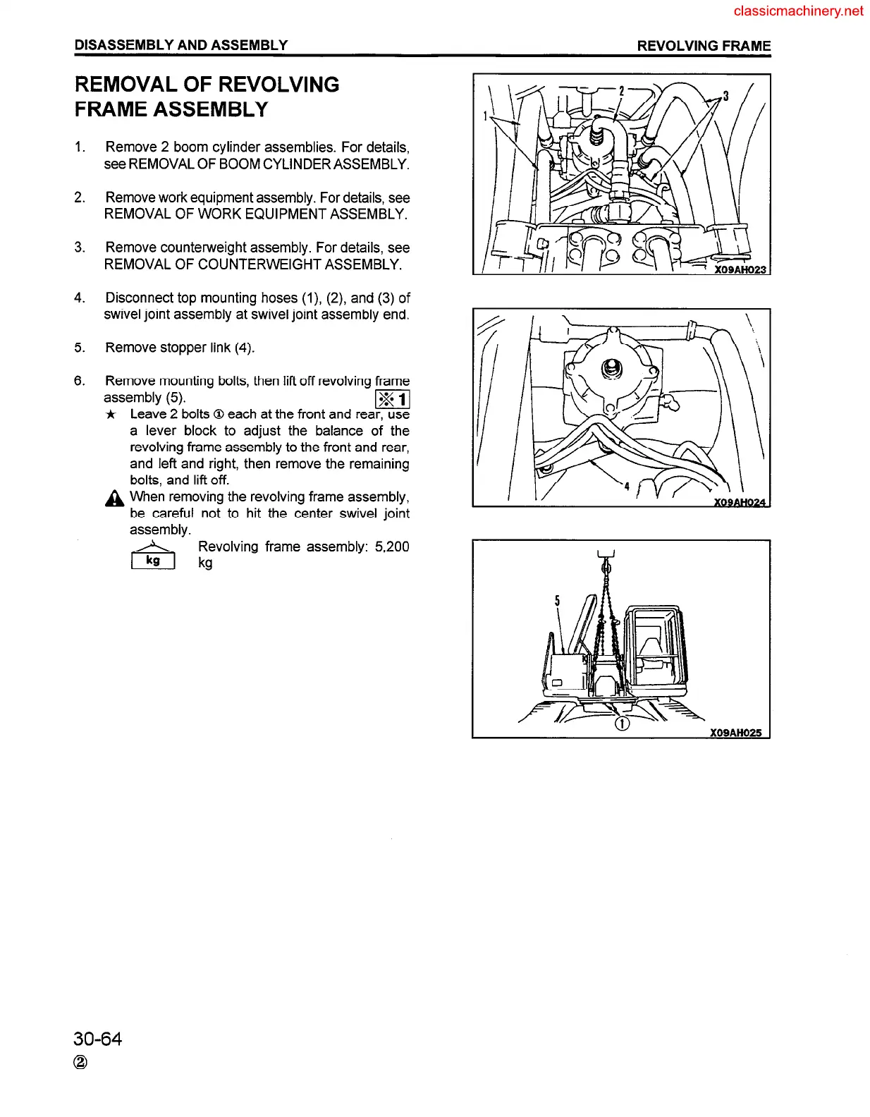
Disconnect top mounting hoses (I), (2) and (3) of
swivel joint assembly at swivel joint assembly end.
Remove stopper link (4).
Remove mounting bolts, then lift off revolving frame
assembly (5).
1
*
A
Leave 2 bolts 0 each at the front and rear, use
a lever block to adjust the balance of the
revolving frame assembly to the front and rear,
and left and right, then remove the remaining
bolts, and lift off.
When removing the revolving frame assembly,
be careful not to hit the center swivel joint
assembly.
Revolving frame assembly: 5,200
kg
30-64
0
 Loading...


