DISASSEMBLY AND ASSEMBLY
PRESSURE COMPENSATION VALVE
DISASSEMBLY OF PRESSURE
COMPENSATION VALVE
ASSEMBLY
(A-D1
0
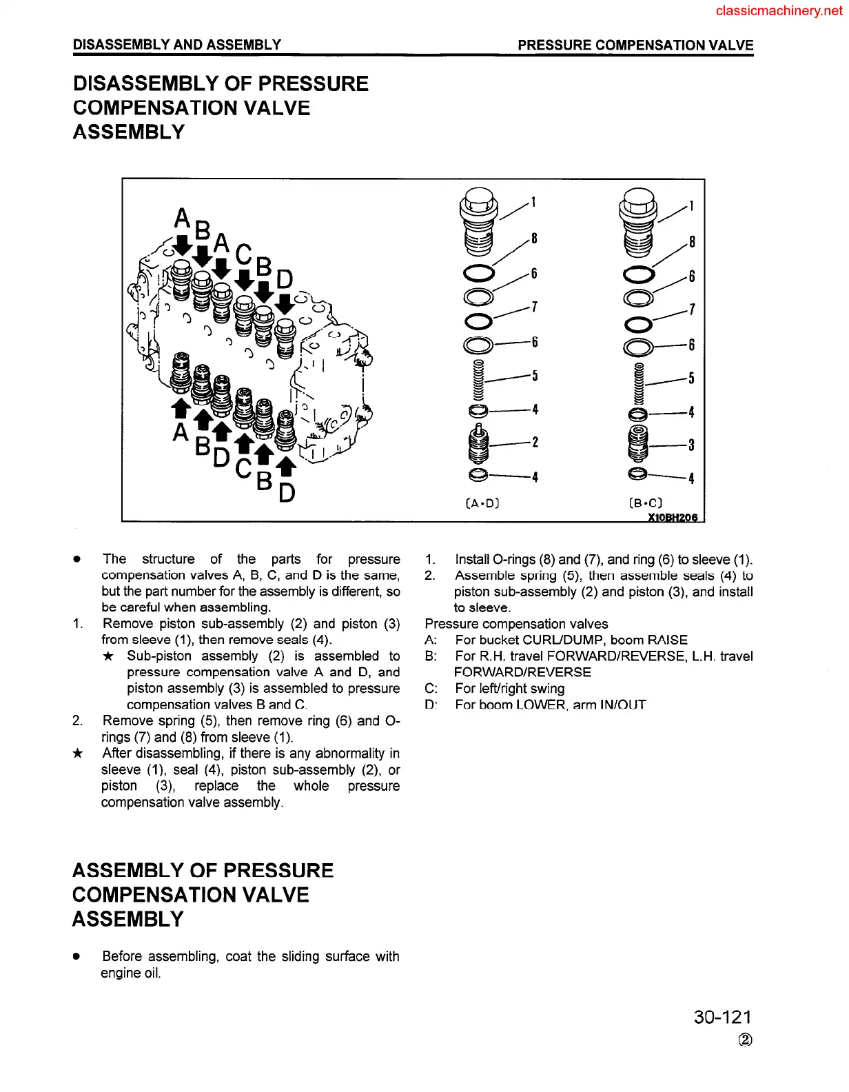
The structure of the parts for pressure
compensation valves A, B, C, and D is the same,
but the part number for the assembly is different, so
be careful when assembling.
1.
Remove piston sub-assembly (2) and piston (3)
from sleeve (I), then remove seals (4).
* Sub-piston assembly (2) is assembled to
pressure compensation valve A and D, and
piston assembly (3) is assembled to pressure
compensation valves B and C.
2. Remove spring (5), then remove ring (6) and O-
rings (7) and (8) from sleeve (1).
* After disassembling, if there is any abnormality in
sleeve (I), seal (4), piston sub-assembly (2) or
piston (3) replace the whole pressure
compensation valve assembly.
ASSEMBLY OF PRESSURE
COMPENSATION VALVE
ASSEMBLY
0
Before assembling, coat the sliding surface with
engine oil.
1. Install O-rings (8) and (7), and ring (6) to sleeve (1).
2.
Assemble spring (5), then assemble seals (4) to
piston sub-assembly (2) and piston (3), and install
to sleeve.
Pressure compensation valves
A: For bucket CURL/DUMP, boom RAISE
B: For R.H. travel FORWARD/REVERSE, L.H. travel
FORWARD/REVERSE
C: For left/right swing
D: For boom LOWER. arm IN/OUT
30-121
0
 Loading...


