DISASSEMBLY AND ASSEMBLY
TRACK SHOE
REMOVAL OF TRACK SHOE
ASSEMBLY
1.
2.
3.
4.
5.
Stop machine at a point where master pin is
midway between idler and carrier roller, and where
there is space to lay out track assembly on ground.
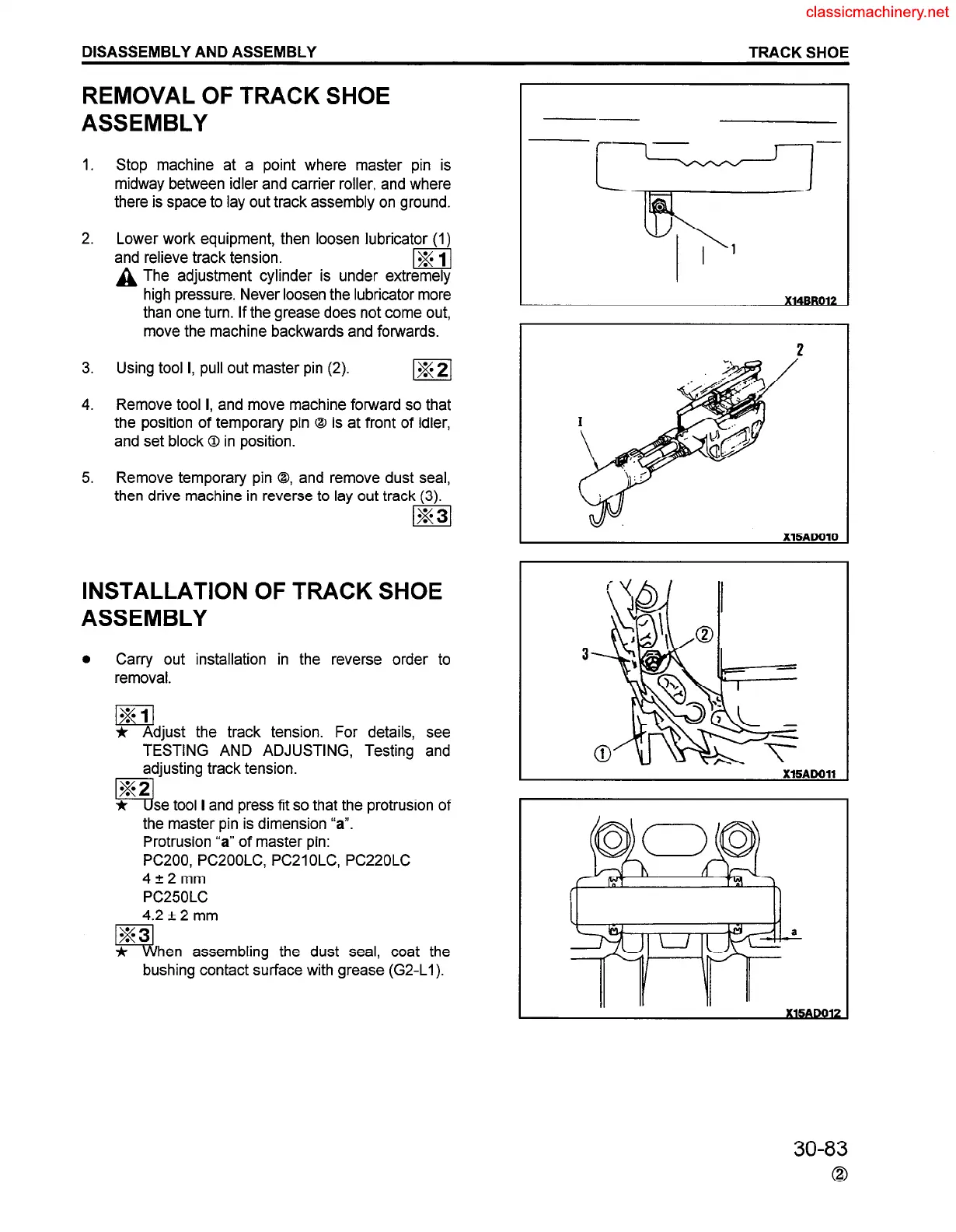
Lower work equipment, then loosen lubricator (1)
and relieve track tension.
m/
A The adjustment cylinder is under extremely
high pressure. Never loosen the lubricator more
than one turn. If the grease does not come out,
move the machine backwards and forwards.
Using tool I, pull out master pin (2).
m
Remove tool I, and move machine forward so that
the position of temporary pin 0 is at front of idler,
and set block 0 in position.
Remove temporary pin Q, and remove dust seal,
then drive machine in reverse to lay out track (3).
INSTALLATION OF TRACK SHOE
ASSEMBLY
0
Carry out installation in the reverse order to
removal.
* Adjust the track tension. For details, see
TESTING AND ADJUSTING, Testing and
adjusting track tension.
se tool I and press fit so that the protrusion of
the master pin is dimension “a”.
Protrusion ‘a” of master pin:
PC200, PC2OOLC, PC21 OLC, PC22OLC
4*2mm
PC25OLC
4.2 + 2 mm
hen assembling the dust seal, coat the
bushing contact surface with grease (G2-Ll).
30-83
0
 Loading...


