DISASSEMBLY AND ASSEMBLY
ENGINE. HYDRAULIC PUMP
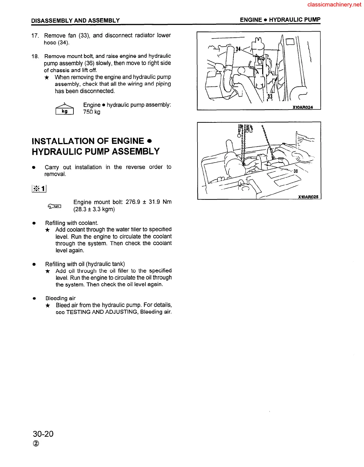
17. Remove fan (33), and disconnect radiator lower
hose (34).
18. Remove mount bolt, and raise engine and hydraulic
pump assembly (36) slowly, then move to right side
of chassis and lift off.
j,
When removing the engine and hydraulic pump
assembly, check that all the wiring and piping
has been disconnected.
Engine l hydraulic pump assembly:
750 kg
INSTALLATION OF ENGINE.
HYDRAULIC PUMP ASSEMBLY
0
Carry out installation in the reverse order to
removal.
\
Engine mount bolt: 276.9 f 31.9 Nm
I
r
.,J
XlOARO25
m
(28.3 f 3.3 kgm)
Refilling with coolant.
*
Add coolant through the water filler to specified
level. Run the engine to circulate the coolant
through the system. Then check the coolant
level again.
Refilling with oil (hydraulic tank)
j, Add oil through the oil filler to the specified
level. Run the engine to circulate the oil through
the system. Then check the oil level again.
Bleeding air
*
Bleed air from the hydraulic pump. For details,
see TESTING AND ADJUSTING, Bleeding air.
30-20
0
 Loading...


