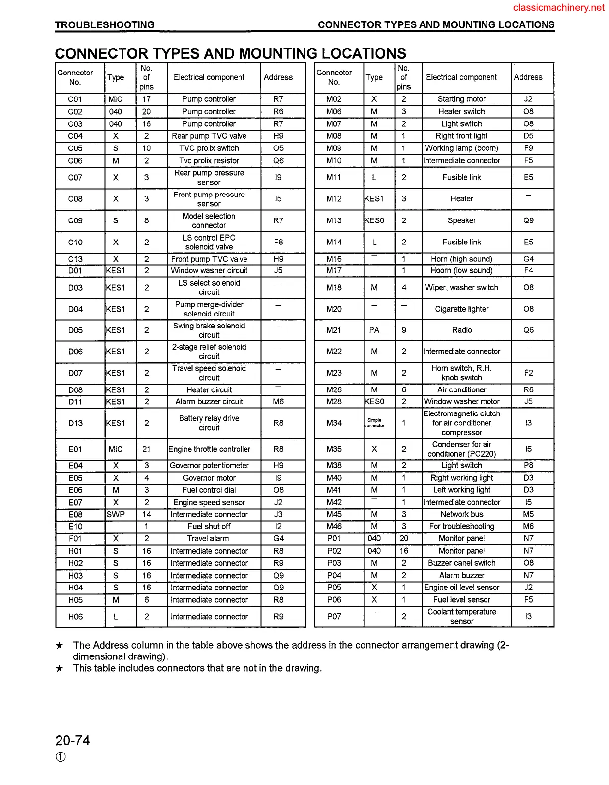
CONNECTOR TYPES AND MOUNTING LOCATIONS
1 Co!ictor 1 Type 1 o:s 1 Electrical component 1 Address
:onnector
No. 1 Type 12s 1 Electrical component I Address
C
co1 (MIC 1 17 1 Pump controller 1 R7
co2 I 040 I 20 I Pump controller 1 R6
MO2
IX I2 I
Starting motor
1 J2
MO6
1 M I 3 I Heater switch I 08
co3
I 040 I 16 I Pump controller 1 R7
co4
lx I2
l Rear pump TVC valve I H9
MO7
IM I2 I
Light switch 1 08
MO8
I M I 1 1 Right front light 1 D5
co5
CO6
1 s I 10 1 TVC prolix switch 1 05
IM 12
1 Tvc prolix resistor
I Q6
MO9
Ml0
I M I 1 1 Working lamp (boom) I F9
1 M 1 1 IIntermediate connector I F5
I
co7 1 x 1 3 1 RearP~;;s~- 1 I9 Ml1 IL 12 1 Fusible link
I
E5
CO8 X
3
Front pump pressure
I5
sensor
co9 S 8
Model selection
connector
R7
Ml2 KESI 3 Heater
-
Ml3 KESO 2 Speaker
Q9
I Cl0 I x I 2 I ~~;;g I F8
Ml4 1 L 1 2 1
Fusible link E5
Cl3
Ix I2
l Front pump TVC valve I H9
DO1 IKESI I 2
I Window washer circuit I J5
Ml6
Ml7
_
1 1 I Horn (high sound)
1 G4
_
I 1 I Hoorn (low sound)
1 F4
1 DO3 IKESI 1 2 1 Ls se;;;;;enoid 1 -
~18 I M I 4 1 Wiper, washer switch I 08
M20 I - ( - I Cigarette lighter I 08
M21
M22
PA 9 Radio
Q6
M 2
Intermediate connector
_
I I I I
M23 M 2
Horn switch, R.H.
knob switch
F2
t DO8
IKESI I 2 Heater circuit
_
M26
I M I 6 I Air conditioner I R6
Dll
D13
EOI
E04
KESI 2
Alarm buzzer circuit M6
KESI 2
Battery relay drive
circuit
R8
MIC 21
Engine throttle controller R8
X
3 Governor potentiometer H9
M28 KESO 2
M34 ,:$$,, 1
Window washer motor
Electromagnetic clutch
for air conditioner
compressor
J5
13
M35
M38
X 2
Condenser for air
conditioner (PC220)
I5
M 2 Liaht switch P8
M40 M 1
Right working light
D3
M41 M
1 Left working light
D3
M42
_
1 Intermediate connector I5
M45
IM I3 I
Network bus 1 M5
M46
I M I 3 I For troubleshooting I ~6
FOI
Ix I2
Travel alarm 1 G4
HOI
I S I 16 I Intermediate connector I ~8
PO1 040 20 Monitor panel N7
PO2 040 16 Monitor panel N7
PO3 M 2 Buzzer cane1 switch 08
I HO2 i S I 16 I Intermediate connector I R9
HO3
IS 116 1 Intermediate connector
1 Q9
HO4
I S I 16 I Intermediate connector I Q9
PO4
IM I2 I
Alarm buzzer 1 N7
PO5 I X I 1 IEngine oil level sensor I J2
PO6 X
PO7 -
1 Fuel level sensor F5
2
Coolant temperature
I3
sensor
HO5
HO6
M 6
Intermediate connector
R8
L
2 Intermediate connector R9
* The Address column in the table above shows the address in the connector arrangement drawing (2-
dimensional drawing).
* This table includes connectors that are not in the drawing.
20-74
0
 Loading...


