DISASSEMBLY AND ASSEMBLY
BOOM CYLINDER
INSTALLATION OF BOOM
CYLINDER ASSEMBLY
Carry out installation in the reverse order to
removal.
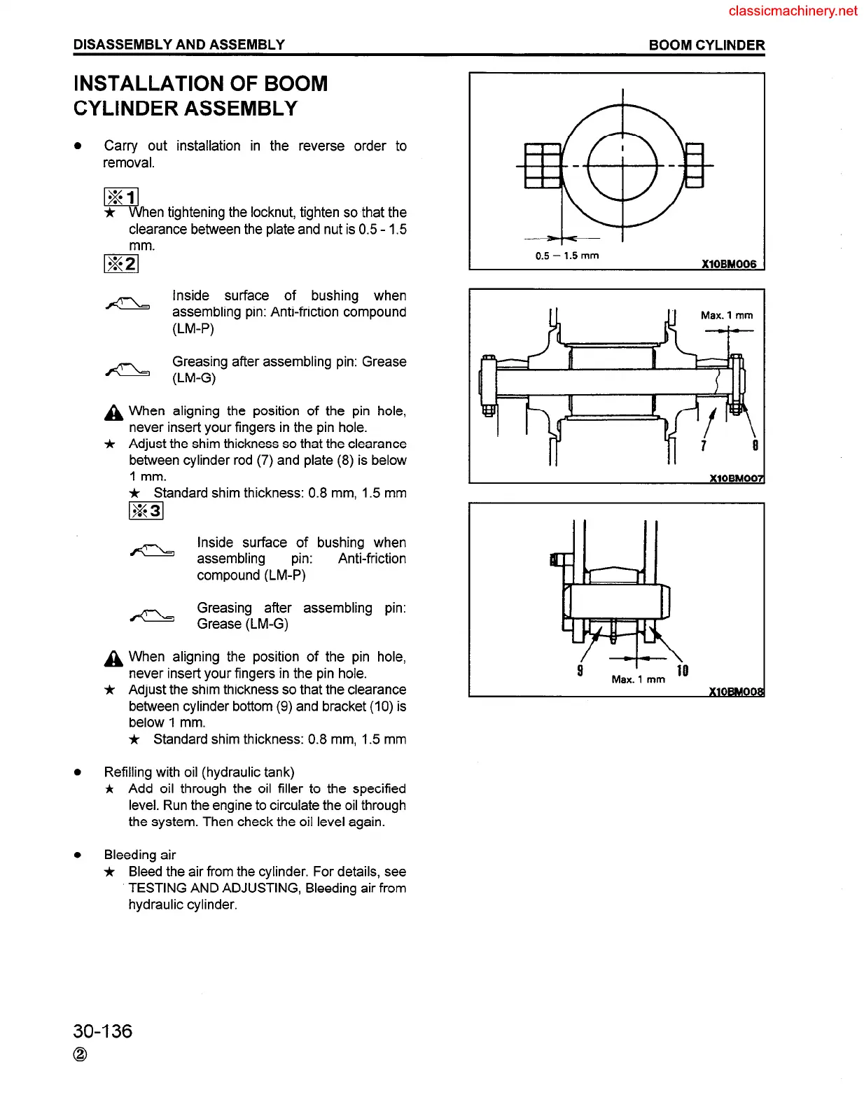
en tightening the locknut, tighten so that the
clearance between the plate and nut is 0.5 - 1.5
mm.
m
A
Inside surface of bushing when
assembling pin: Anti-friction compound
(LM-P)
Greasing after assembling pin: Grease
A (LM-G)
A When aligning the position of the pin hole,
never insert your fingers in the pin hole.
* Adjust the shim thickness so that the clearance
between cylinder rod (7) and plate (8) is below
1 mm.
* Standard shim thickness: 0.8 mm, 1.5 mm
m
Inside surface of bushing when
a assembling
pin:
Anti-friction
compound (LM-P)
Greasing after assembling pin:
- Grease (LM-G)
A When aligning the position of the pin hole,
never insert your fingers in the pin hole.
* Adjust the shim thickness so that the clearance
between cylinder bottom (9) and bracket (IO) is
below 1 mm.
* Standard shim thickness: 0.8 mm, 1.5 mm
Refilling with oil (hydraulic tank)
j, Add oil through the oil filler to the specified
level. Run the engine to circulate the oil through
the system. Then check the oil level again.
Bleeding air
j, Bleed the air from the cylinder. For details, see
TESTING AND ADJUSTING, Bleeding air from
hydraulic cylinder.
0.5 - 1.5 mm
XlOBM006
I
Max. 1 mm
io
30-136
0
 Loading...


