DISASSEMBLY AND ASSEMBLY
SPECIAL TOOL LIST
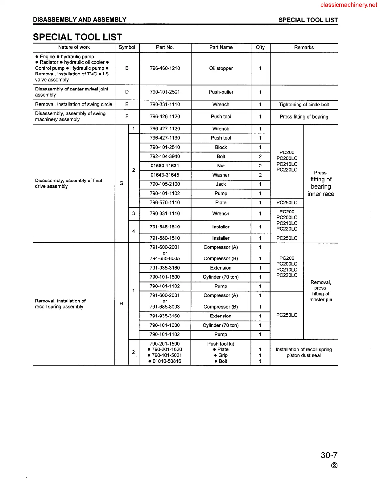
SPECIAL TOOL LIST
I
Symbol Part No.
Part Name
I Q’@ I
Remarks
Nature of work
l Engine l hydraulic pump
l Radiator l hydraulic oil cooler l
Control pump l Hydraulic pump l
Removal, installation of TVC l LS
valve assembly
B 796-460-1210 Oil stopper
I
Push-puller
I
Disassembly of center swivel joint
assembly
D
790-101-2501
790-331-l 1 IO
Wrench
I 1 I
Tightening of circle bolt
Removal, installation of swing circle
Disassembly, assembly of swing
machinery assembly
G
E
F
1
-
2
-
3
-
4
-
I
H
-
2
-
796-426-I 120 Push tool
1 Press fitting of bearing
796427-l 120 Wrench
I
796-427-I 130 Push tool
I
790-l 01-2510
792-I 04-3940
01580-11631
Press
fitting of
bearing
inner race
01643-31645
Disassembly, assembly of final
drive assembly
790-I 05-2100
Jack
1 I 1
790-101-1102 Pump
I 1 I
796-570-l I IO Plate
I
PC25OLC
790-331-I 110
791-545-1510
791-580-1510
791-600-2001
794-6:;-8005
Installer
Compressor (A)
Compressor (B)
Extension
Cylinder (70 ton)
I
PC250LC
I
I
PC200
PCZOOLC
I
PC21 OLC
I
PC22OLC
791-935-3160
790-101-1600
Removal,
press
fitting of
master pin
790-101-1102 Pump
I i-1
791-600-2001
791-6:;-8003
791-935-3160
Removal, installation of
recoil spring assembly
790-101-1600 Cylinder (70 ton) I I I
790-101-1102 Pump
I 1 I
790-201 -I 500
Push tool kit
. 790-201 -I 620
0 Plate
l 790-l 01-5021 l Grip
.OIOIO-50816
l Bolt
I Installation of recoil spring
I
piston dust seal
I
30-7
0
 Loading...


