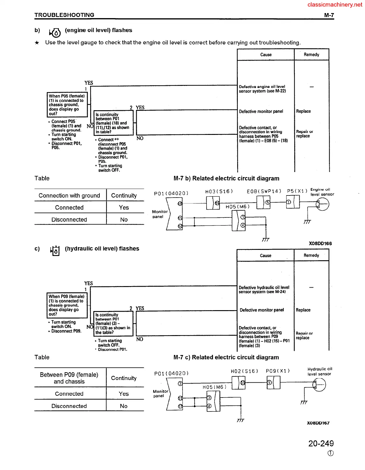
b)
0
6 (engine oil level) flashes
* Use the level gauge to check that the engine oil level is correct before carrying out troubleshooting.
Cause
Remedy
3efective engine oil level
sensor system (see M-22)
-
When PO5 (female)
(1) is connected to
2YEs
Is continuity
between PO1
(female) (18) and -
fllLf12) as shown
. Connect PO5
(female) (1) and 1
chassis ground.
l Turn starting
in table?
II
switch ON.
NO
l Disconnect POl,
l Connect tf
disconnect PO5
PO5
(female) (1) and
chassis ground.
l Disconnect POl,
PO5.
l Turn starting
switch OFF.
Table
teplace
Defective contact, or
disconnection in wiring
harness between W5
(female) (1) - E08 (5) - (18)
lepair or
eplace
M-7 b) Related electric circuit diagram
EOB(SWP14)
or
Connection with ground Continuity
Connected Yes
Disconnected
X08DD166
cl
cl
6 (hydraulic oil level) flashes
Remedy
Cause
Y
1
5
When PO9 (female)
(1) is connected to
chassif ground,
cllte,s display go
Defective hydraulic oil level
sensor system lsee M-24)
. T~;x&tt$g
l Disconnect w9.
f
2YEs
Is continuity
between PO1
- (female) 13) -
) Ulh3) as shown in
the table?
l Turn starting
switch OFF.
l Disconnect F’Ol.
NO
Defective monitor panel
Defective contact, or
disconnection in wiring
’ harness between PO9
(female) (1) - HO2 (15) - PO1
(female) 13)
M-7 c) Related electric circuit diagram
-
repair or
eplace
Table
Hydraulic oil
level sensor
POl(O4020)
H02(516)
PO9fXl)
Monit
panel
X08DD167
Between PO9 (female)
and chassis
Continuity
Connected
I
Yes
Disconnected
I
No
20-249
0
 Loading...


