DISASSEMBLY AND ASSEMBLY SWING CIRCLE
INSTALLATION OF SWING
CIRCLE ASSEMBLY
0
Carry out installation in the reverse order to
removal.
m/
1 st pass:
2nd pass:
Thread of swing circle mounting bolt:
Thread tightener (LT-2)
Swing circle mounting bolt: PC200-6,
PC2OOLC-6, PC21 OLC-6, PC22OLC-6
Tighten to 191.3 f 19.6 Nm (19.5 f 2
kgm)
1)
l
2)
i)
ii)
iii)
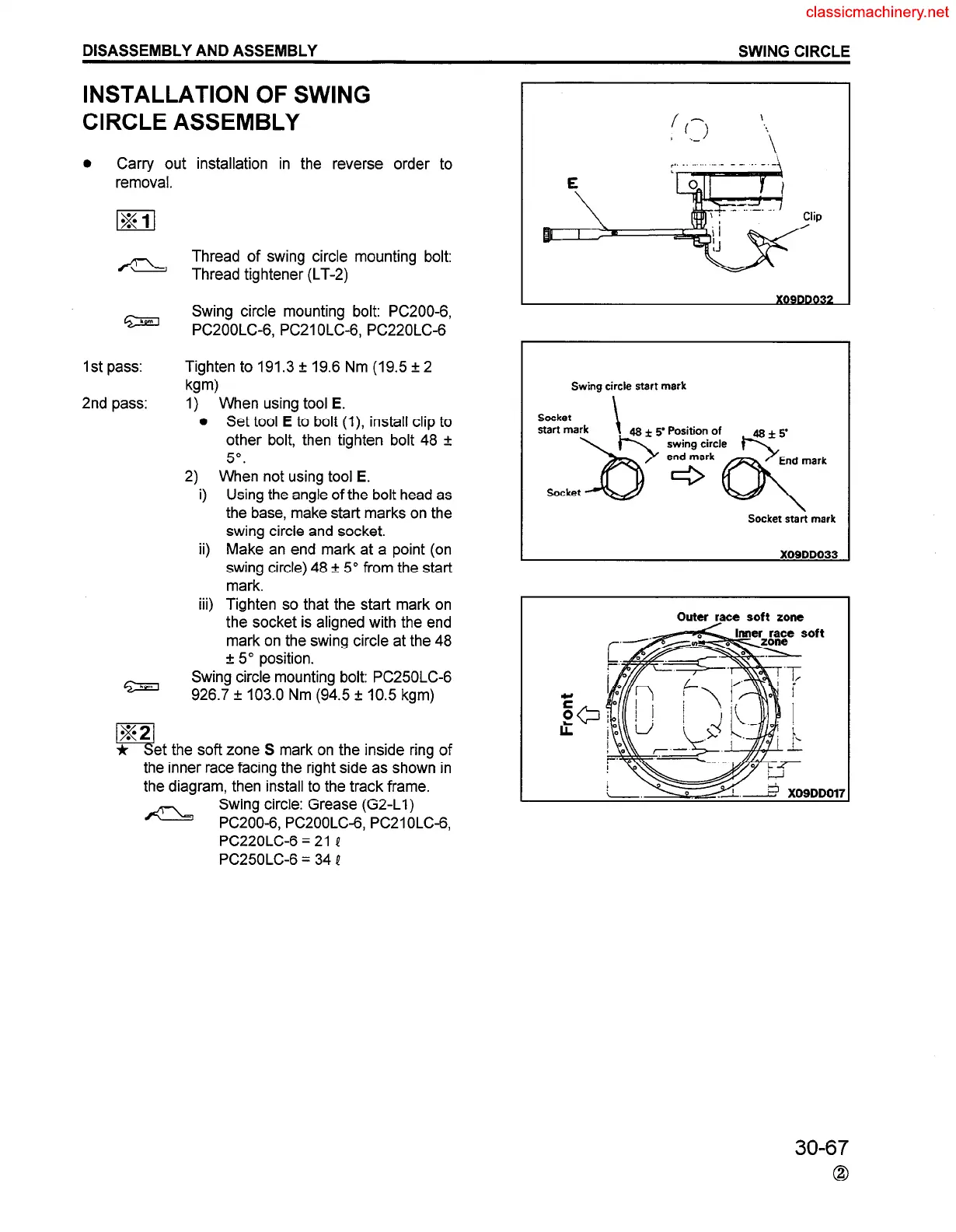
When using tool E.
Set tool E to bolt (I), install clip to
other bolt, then tighten bolt 48 f
5”.
When not using tool E.
Using the angle of the bolt head as
the base, make start marks on the
swing circle and socket.
Make an end mark at a point (on
swing circle) 48 + 5” from the start
mark.
Tighten so that the start mark on
the socket is aligned with the end
mark on the swing circle at the 48
f 5” position.
Swing circle mounting bolt: PC250LC-6
926.7 f 103.0 Nm (94.5 + 10.5 kgm)
G!
22
et the soft zone S mark on the inside ring of
the inner race facing the right side as shown in
the diagram, then install to the track frame.
a
Swing circle: Grease (G2-Ll)
PC200-6, PC2OOLC-6, PC21 OLC-6,
PC22OLC-6 = 21 Q
PC25OLC-6 = 34 P
lip
Swing circle start mark
Socket
start mark
socket&;zz2z$eerk
Socket start mark
Outer raoe soft zone
30-67
0
 Loading...


