DISASSEMBLY AND ASSEMBLY
HYDRAULIC TANK
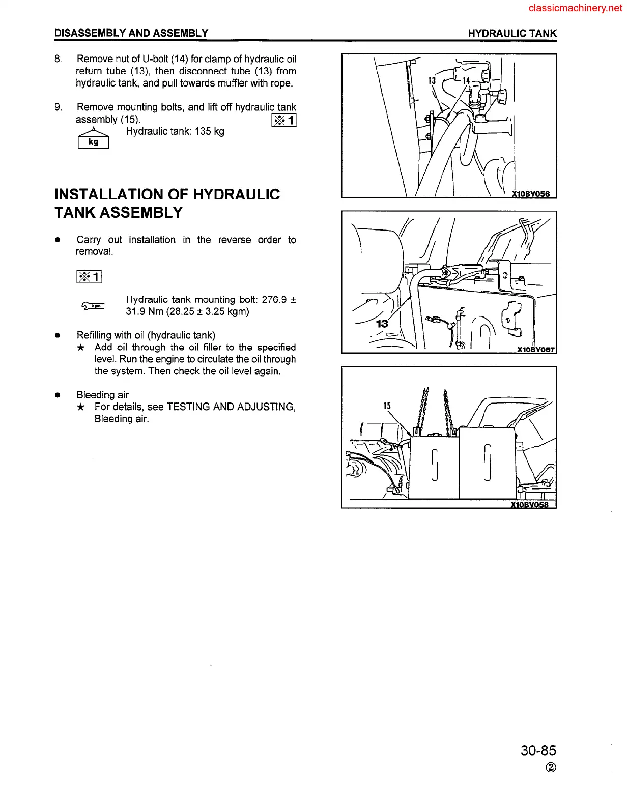
8. Remove nut of U-bolt (14) for clamp of hydraulic oil
return tube (13) then disconnect tube (13) from
hydraulic tank, and pull towards muffler with rope.
9. Remove mounting bolts, and lift off hydraulic tank
assembly (15).
Hydraulic tank: 135 kg
INSTALLATION OF
TANK ASSEMBLY
Carry out installation in
removal.
HYDRAULIC
the reverse order to
Hydraulic tank mounting bolt: 276.9 f
31.9 Nm (28.25 f 3.25 kgm)
Refilling with oil (hydraulic tank)
jr Add oil through the oil filler to the specified
level. Run the engine to circulate the oil through
the system. Then check the oil level again.
Bleeding air
* For details, see TESTING AND ADJUSTING,
Bleeding air.
lOBV056
30-85
0
 Loading...


