301ENGINE
ASSEMBLY
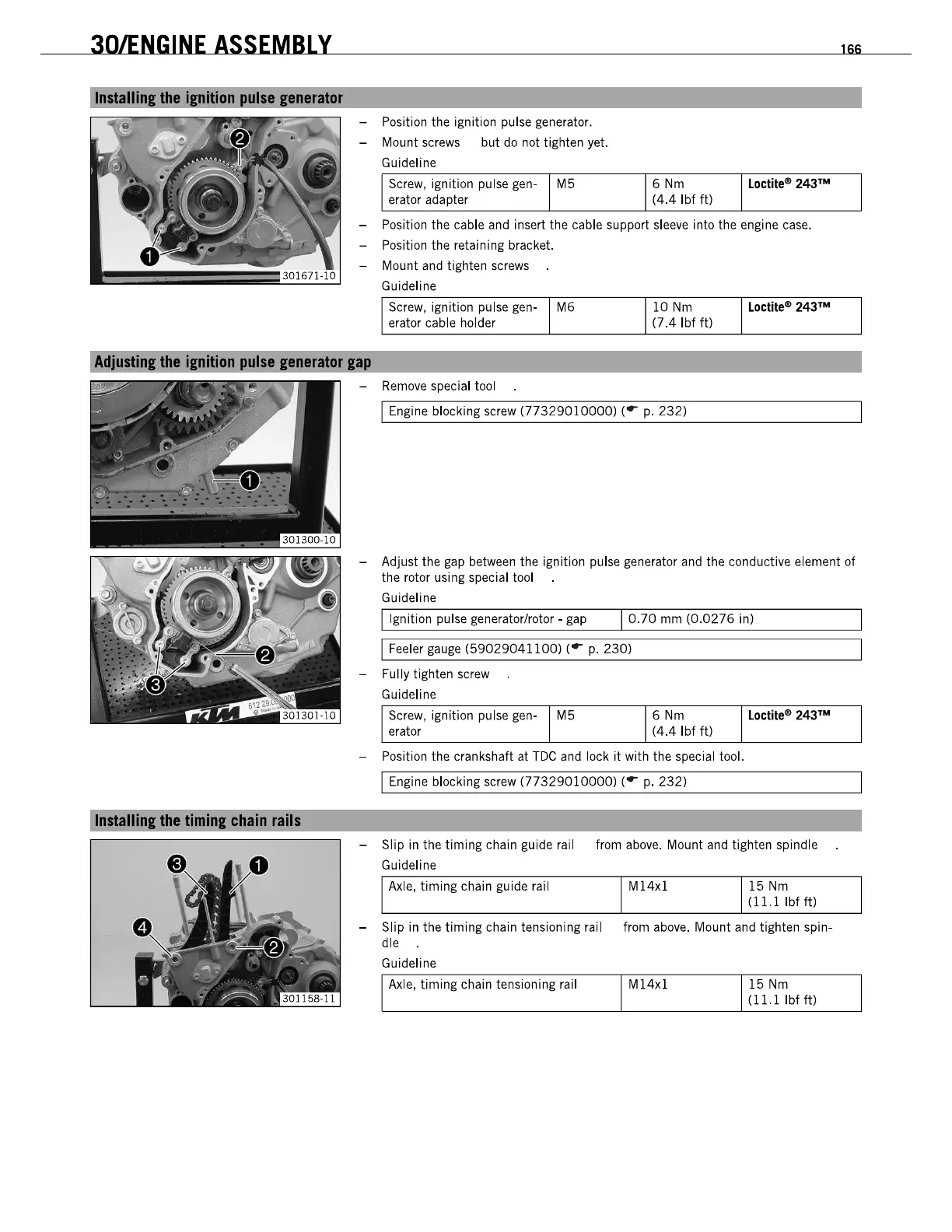
Installinllha
timinl
chain
rails
- Position the ignition pulse generator.
- Mount screws but
do
not tighten yet.
Guideline
Screw, ignition pulse gen- M5
6Nm
Loctitee
243
111
erator adapter (4.4 Ibf
ft)
- Position the cable
and
insert the cable support
sleeve
into the engine
case.
- Position the retaining bracket.
- Mount and tighten
screws
Guideline
Screw, ignition pulse gen- M6
erator cable holder
-
Remove
special tool
10
Nm
(7.4lbfft)
I Engine blocking screw
(77329010000)
('
r
p.
232)
166
- Adjust the gap between the ignition pulse generator
and
the conductive element of
the rotor using special tool
Guideline
I Ignition pulse generator/rotor - gap I
0.70
mm
(0.0276
in)
I Feeler
gauge
(59029041100)
('
r
p.
230)
- Fully tighten screw
Guideline
Screw, ignition pulse gen- M5
erator
6Nm
(4.4 Ibf ft)
- Position the crankshaft at
TDC
and
lock
it
with the special tool.
I Engine blocking screw
(77329010000)
(
or
p.
232)
Loctitee
243
111
- Slip
in
the timing chain guide rail from
above.
Mount
and
tighten spindle
Guideline
Axle,
timing chain guide rail M14x1 15
Nm
(11.1
Ibf ft)
- Slip
in
the timing chain tensioning rail from
above.
Mount and tighten spin-
dle
Guideline
Axle,
timing chain tensioning rail M14x1 15
Nm
(ll.1Ibfft)

 Loading...