04LSHOCK
ABSORBER,
SWINGARM
56
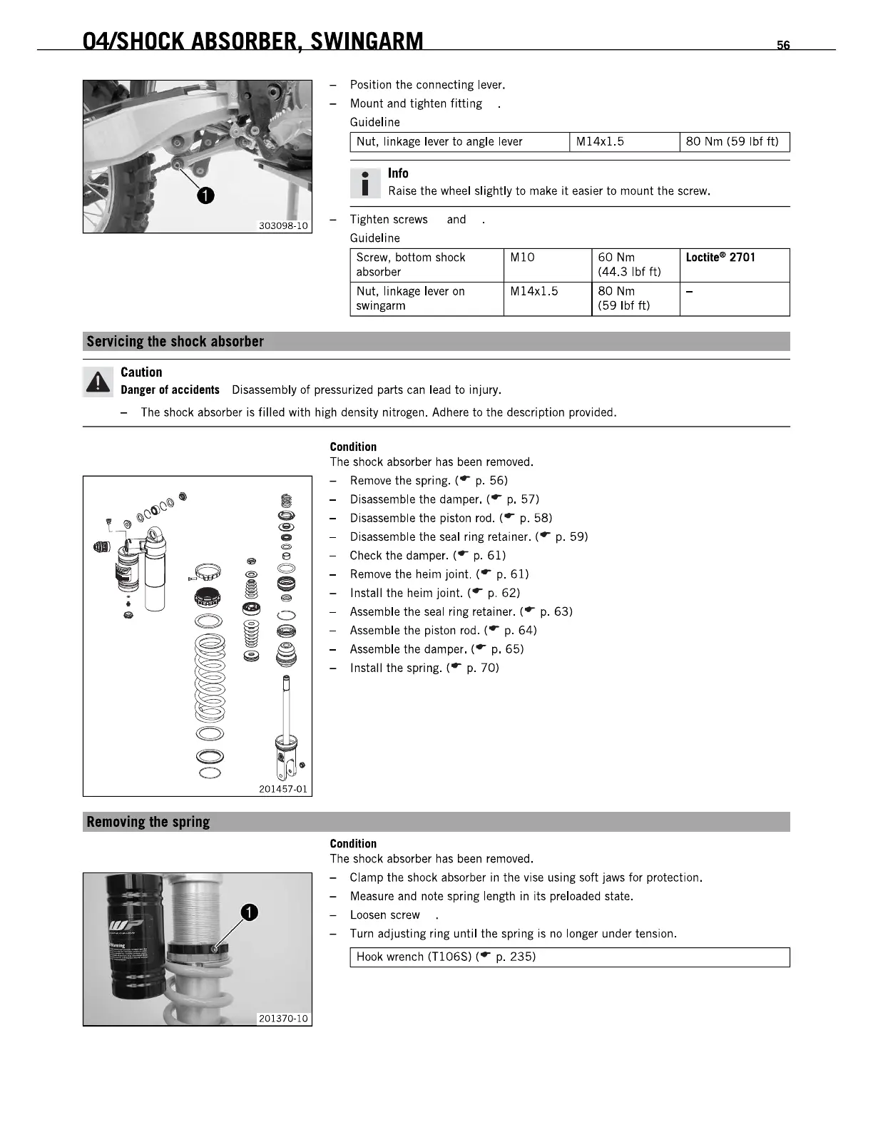
- Position the connecting lever.
- Mount and tighten
fitting
Guideline
I Nut, lin
kage
lever to angle lever
I M14x1.5
180
Nm
(59
Ibf ft)
_
Info
I
Raise
the wheel slightly to make
it
easier
to
mount the screw.
- Tighten screws and
Guideline
Screw, bottom shock
MlO
60
Nm
Locti!.-
2701
absorber
(44.3
Ibf
It)
Nut,
Ii
n
kage
lever
on
M14x1.5
80
Nm
-
5wingarm
(59
Ibf
ft)
SlIlYicinl
thllshuck
absortJar
Caution
Danger
of accidents Disassembly
of
pressurized parts can lead to injury.
- The shock absorber is filled with high density nitrogen. Adhere
to
the description provided.
•
6J~a
.;~
...
~O
•
OJ
OJ
OJ
o
RllmDYinl
thll
rinl
I
@
®
0
C>
..
e
@
<OJ
~
e
'"
~O
~
~
@e
•
201457-01
Condition
The shock absorber
has
been
removed.
-
Remove
the spring. (
.-
p.
56)
- Disassemble the damper. (
.-
p.
57)
- Disassemble the piston rod. (
.-
p.
58)
- Disassemble the seal ring retainer. (
.-
p.
59)
- Check the damper. (
.-
p.
61)
-
Remove
the heim joint. (
.-
p.
61)
- Install the heim joint. (
.-
p.
62)
- Assemble the seal ring retainer. (
.-
p.
63)
- Assemble the piston rod. (
.-
p.
64)
- Assemble the damper. (
.-
p.
65)
- Install the spring. (
.-
p.
70)
Condition
The shock absorber
has
been
removed.
- Clamp the shock absorber in the vise using soft jaws for protection.
- Measure and note spring length in its preloaded state.
-
Loosen
screw
- Turn adjusting ring until the spring is
no
longer under tension.
I Hook wrench
(TlD6S)
(
.-
p.
235)
 Loading...