rSO2 Tiles Regional Oxygen Saturation (rSO2) (Optional)
3 - 6 Addendum to V Series Operating Instructions
NOTE: Refer to "Changing VDI Modes" on page 5-4 of the V Series Operating
Instructions for additional information.
5. Turn on the INVOS Monitor.
3.3.3 Configuring the INVOS Monitor Serial Port
Before configuring the V 12/V 21 monitor to display rSO2, the INVOS Monitor serial port must be
properly configured to communicate bidirectionally with the V 12/V 21. Using the operating
instructions from the INVOS Monitor, verify the following serial port settings:
3.4 rSO2 Tiles
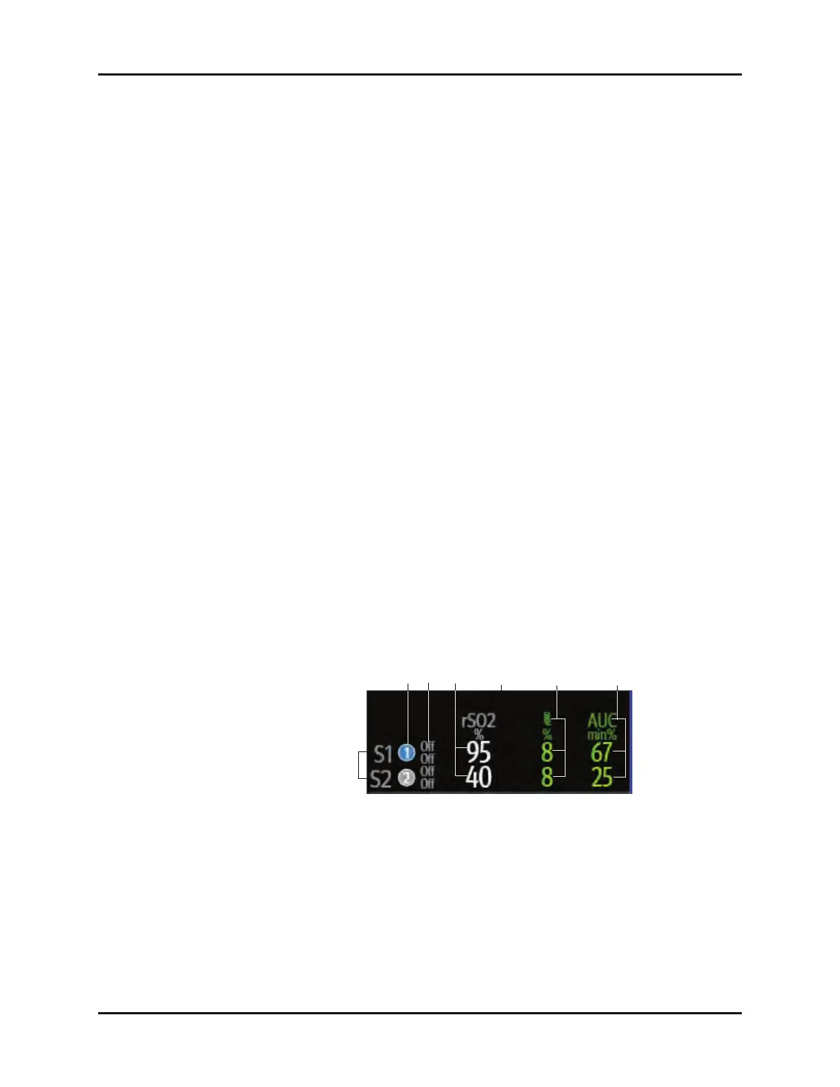
3.4.1 rSO2 Digital Tile Layout
The rSO2 digital tile displays:
1. Data channel label
2. Channel indicator
3. Upper and lo
wer alarm limits
4. rSO2 values
5. Message area
6. rSO2 Baseline and values
7. Area Under Curve (AUC) values
FIGURE 3-5 Exa
mple rSO2 Tile (Two-Channel Monitoring)
Baud Rate 9600
Parity None
Stop Bits 1
Data Bits 8
Flow Control Hardware
 Loading...