6.3 Mounting Position
6 - 3
1
OVERVIEW
2
SYSTEM
CONFIGURATION
3
SPECIFICATIONS
4
PART NAME AND
SETTINGS
5
EMC AND LOW
VOLTAGE
DIRECTIVE
6
INSTALLATION
7
WIRING
8
OPTION
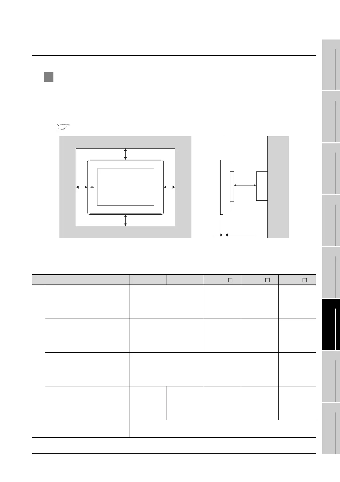
6.3 Mounting Position
1 For installing GOT
When mounting the GOT, the following clearances must be left from the other device.
Depending on the units and cables connected to the GOT, clearances more than the described
dimensions can be required.
Therefore, consider the connector dimensions and bending radius of the cable as well for installation.
For the lead-in allowance for cables at the bottom of the GOT, refer to the following.
Appendix 1 External Dimensions
According to the dimensions in the following table, leave clearances between the GOT and the other
devices. The values enclosed in square brackets apply to the case where no other equipment
generating radiated noise (such as a contactor) or heat is installed near the GOT. However, keep the
ambient temperature of the GOT to 55°C or lower.
(Continued to next page)
Type GT1595 GT1585
GT157 GT156 GT155
A
GOT only
50(1.97) or more
[20(0.79) or more]
50(1.97)
or more
[20(0.79)
or more]
50(1.97)
or more
[21(0.83)
or more]26
49(1.93)
or more
Bus connection unit is fitted
50(1.97) or more
[20(0.79) or more]
50(1.97)
or more
[35(1.38)
or more]
50(1.97)
or more
[40(1.57)
or more]
50(1.97)
or more
Serial communication unit fitted
50(1.97) or more
[20(0.79) or more]
50(1.97)
or more
[20(0.79)
or more]
50(1.97)
or more
[21(0.83)
or more]
49(1.93)
or more
RS-422 Conversion unit is fitted
50(1.97)
or more
[20(0.79)
or more]
50(1.97)
or more
[39(1.54)
or more]
53(2.09)
or more
58(2.28)
or more
—
Ethernet communication unit is
fitted
50 (1.97) or more [20 (0.79) or more]
BA
CD
E
Panel thickness:
2 to 4mm
(0.08 to 0.16inch)

 Loading...

