8.16 Attachment
8.16.2 Installing procedure
8 - 59
1
OVERVIEW
2
SYSTEM
CONFIGURATION
3
SPECIFICATIONS
4
PART NAME AND
SETTINGS
5
EMC AND LOW
VOLTAGE
DIRECTIVE
6
INSTALLATION
7
WIRING
8
OPTION
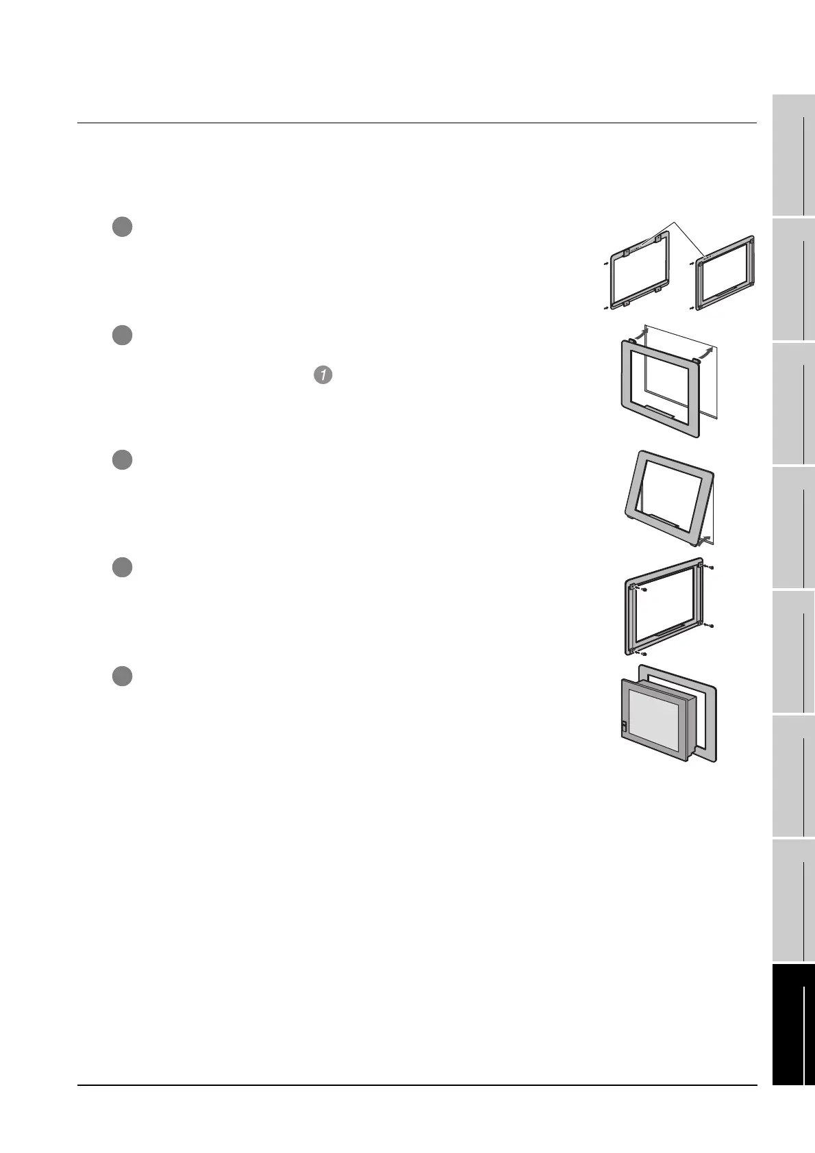
8.16.2 Installing procedure
(1) For GT15-70ATT-98, GT15-60ATT-97, GT15-60ATT-96, GT15-60ATT-87 and GT15-60ATT-77
The following figures show an example of the GT15-60ATT-97 installarion.
Follow the same procedure for installing the other models.
1 The model name is indicated on the attachment.
The upper part of the attachment has the model indication.
(Example of model indication)
2 Hang the two upper hooks on the upper part over the mounting holes in
the control panel.
Refer to the figure shown in .
3 While lifting the attachment upward, hang the two lower hooks on the
lower part of the control panel.
4 Fix the attachment to the control panel with four clamp screws in the
torque range of 0.2 to 0.28N•m.
5 Place the GOT into the attachment from the front, and fix it by tightening
the mounting screws included with the GOT in the torque range of 0.36
to 0.48N•m.
Upper
part
Lower
part
Upper
part
Lower
part
Model

 Loading...

