5.5.1.4 Mixers on the servo side
"Mixers on the servo side" combine up to 8 control functions in one common output
signal. You can assign a unique name to each mixer. It is possible to assign the
output signal to one or more servos using the name of the mixer.
For safety reasons, the mixers are defined and configured in separate main menus.
In this menu, only the travels and other parameters are configured. Only mixers are
shown that are actually used, i.e. that are assigned to a servo.
The mixers are defined in the Setup > Define mixer menu (see section 5.3.7
"Define mixer" on page 105).
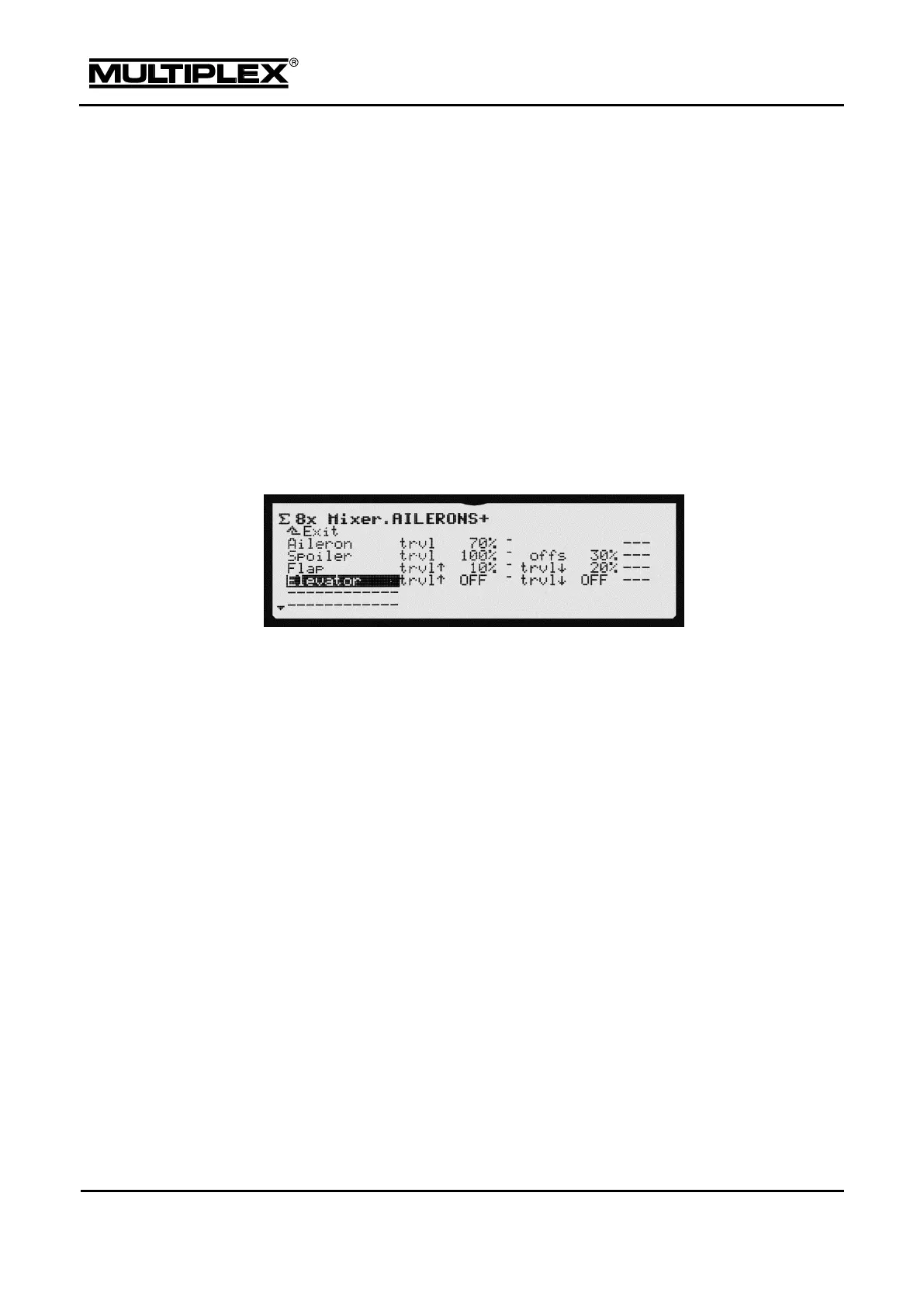
The following example of the AILERONS+ mixer, which is used in the GLIDER+
model template, illustrates how mixers on the servo side are configured.
Each line on the screen has 2 input and 2 display fields:
Aileron: The aileron travel in an upward direction is set here. The differential is
set using A.-Differential. Observe the directions of stick and rudder: Reverse
the travel using the REV/CLR button, if required. In addition, check the differential
direction. Level and direction can be adapted for all aileron inputs using the A.-
Differential mixer. If "Spoiler" is mixed in, you should switch the differential
mode to +SPOILER.
Spoiler: The end-travel of the spoiler on the aileron is configured in addition to
full travel. The direction is determined by the prefix of the set value.
Apply an offset (offs) to shift the zero point of the output signal to make full use of
the servo travel (always in opposite direction of the spoiler).
Flap: Configure the rudder travels separately for up and down using the two set
values.
Elevator: The input is used untrimmed. Configure the rudder travels separately for
up and down using the two set values. Usually, this mixer should be switchable. As
we do not know the type and location of the switches installed in your transmitter it is
not possible to assign switches in the templates. However, you can assign switches
in the Setup > Define mixer menu (see section 5.3.7 "Define mixer" on page 105).

 Loading...