B 1-36
Hydraulics
n'
2
3
4
4130833
Air Valve lnstallation
@ontd)
9.
lnstall
the upper detent on the bottom of the valve
body
with
the two
socket-head screws removed earlier. Tighten
to
1.82-2.27 N.m
(16-20
in.-lb).
10. lnstallthe valve
cap.
Tighten
the valve cap screws to
3-4
N.m
(28-36
in.-lb).
1'1.
Complete Magnet Assembly lnstallation.
Use this
procedure
to replace the
actuator bumper assembly without
removing
the actuator from the unit.
WARNING: Disconnect
and
lock
out line voltage to the unit.
Failure
to observe this warning can result in
personal
injury
or
death.
'1.
Turn
the unit off; then disconnect and lock out
power
to
the
unit.
2. Reduce
the
pump
air
pressure
to
0.
3.
Remove
the
pump
cover.
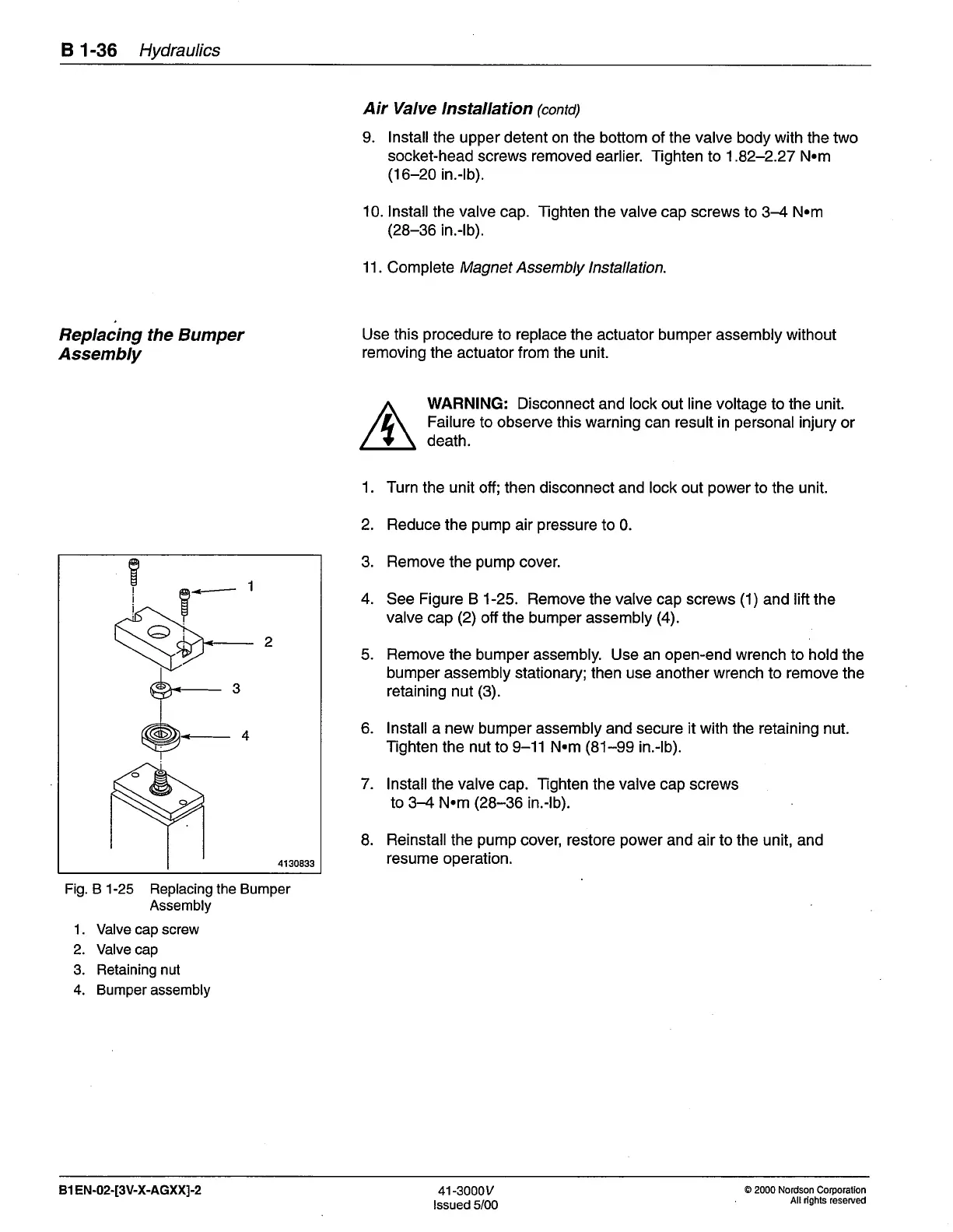
4. See Figure B 1-25. Remove
the
valve
cap screws
(1)
and lift the
valve
cap
(2)
off the bumper assembly
(4).
5.
Remove
the bumper assembly. Use an open-end wrench to hold the
bumper assembly stationary;then use another wrench
to
remove
the
retaining
nut
(3).
6.
lnstall
a new bumper assembly and secure it with
the
retaining
nut.
Tighten
the nut to 9-11 N.m
(81-99
in.-lb).
7.
lnstallthe valve cap. Tighten the valve
cap screws
to 3-4 N.m
(28-36
in.-lb).
8.
Reinstall
the
pump
cover, restore
power
and air to the unit, and
resume operation.
Replacing
the Bumper
Assembly
Fig. B 1-25 Replacing the Bumper
Assembly
'1
. Valve cap screw
2. Valve cap
3. Retaining nut
4. Bumper assembly
B1
EN-02-[3V-X-AGXX]-2
41-3000v
lssued 5/00
O
2000 Nordson Corporation
All
rights
reserved
 Loading...


