Control B 2-33
I
a
5. Remove
the mounting hardware
from the
power
board.
CAUTION: Bisk of equipment
damage.
Do
not bend the XPl
connector
pins.
6.
Starting
from
the edge opposite the XP1
connector, carefully separate'
the
power
board from the
control board. Take care not
to bend the
XP1
connector
pins
that
join
power
board
and control board.
NOTE:
The XP1
connector may remain
attached to the
power
board.
lf
it does, remove
it and attach it to connector
XP3 on the control
board.
NOTE: lf
the optional l/O board is connected
to the control board on
your
unit,
take care not
to damage the l/O board
as
you
remove
the
power
board.
Power
Board lnstallation
1. Remove
the new
board from its
static-safe container. Handle the
board
by
its
edges without
touching any
pins,
wires,
or circuitry.
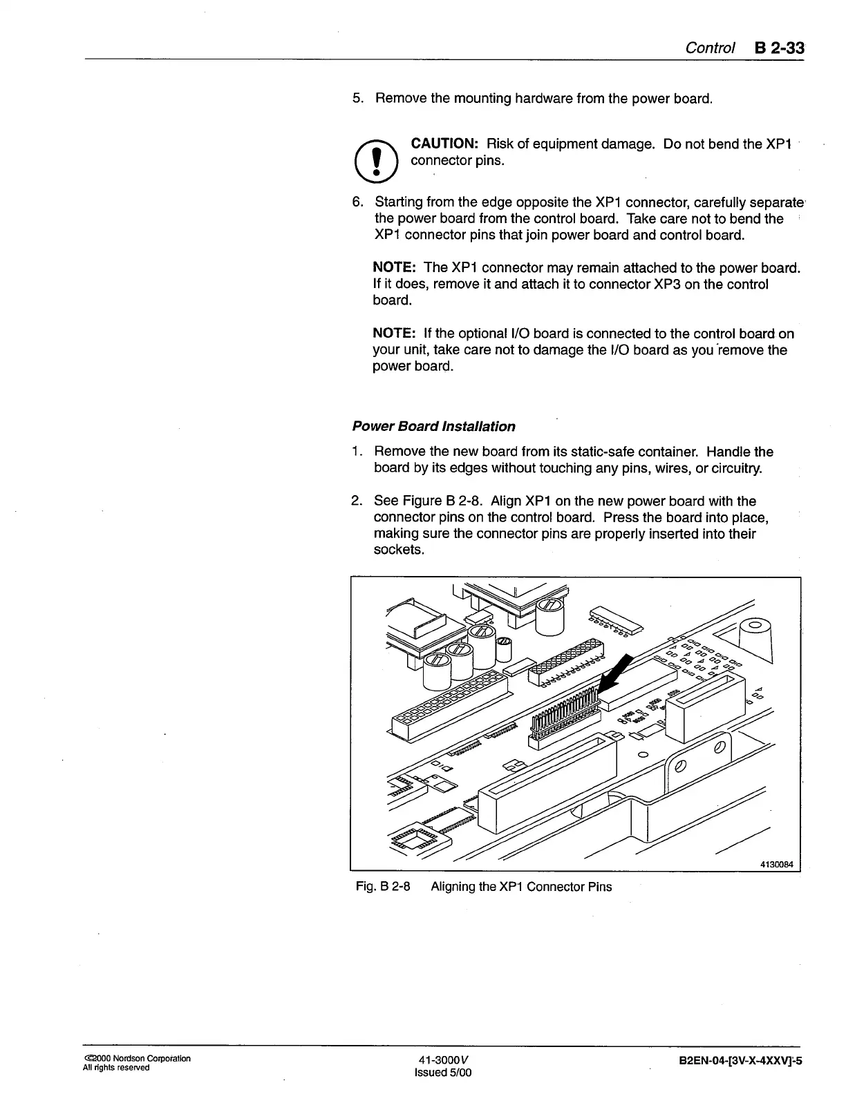
2.
See Figure B 2-8.
Align XPI on the new
power
board with the
connector
pins
on the control
board. Press the board into
place,
making sure the
connector
pins
are
properly
inserted into their
sockets.
Fig. B 2-8 Aligning
the XP1
Connector Pins
oo
oo
oo
oo
4130084
*foio
s!€
o
@00 Nordson
Corpoiallon
All rights reserued
4'l-3000y
lssued 5/00
82 EN-04-[3V-X-4XXV1:.5
 Loading...


