Control
B 2-35
Control Board
lnstallation
1. Remove
the new board from its
static-safe container. Handle the
board
by its edges without
touching any
pins,
wires, or circuitry.
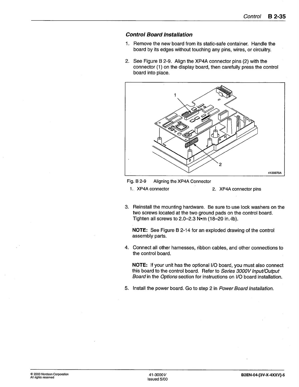
2.
See
Figure
B 2-9.
Align the XP4A connector
pins
(2)
with
the
connector
(1)
on the display board, then carefully
press
the
control
board into
place.
1
2
4130078A
Fig.
B 2-9 Aligning
the XP4A
Connector
1. XP4A
connector
2. XP4A connector
pins
3. Reinstallthe mounting
hardware. Be
sure to use lock washers on
the
two
screws located
at the two
ground pads
on
the control board.
Tighten
allscrews to2.0-2.3 N.m
(18-20
in.-lb).
NOTE:
See
Figure
B 2-14 for an exploded
drawing of the control
assembly
parts.
4.
Connect all other harnesses, ribbon
cables, and
other connections to
the control
board.
NOTE: lf
your
unit has the
optional l/O board,
you
must also connect
this
board to the
control board. Refer
to Series 3000V lnput/Output
Boardinthe
Options section for instructions
on l/O board installation.
5.
lnstallthe
power
board.
Go
to step 2in Power
Board lnstallation.
@
2000 Nordson Corporation
All dghts reserued
41-3000y
lssued
5/00
82EN-04-[3V-X-4XXVI-5
 Loading...


