B 2-38 Control
Operator Panel lnstallation
1.
Remove the new
operator
panel
from its static-safe
container.
Handle the
panel
by
its
edges without touching
the ribbon cable
pins.
2. With
clean hands,
peel
the
paper
backing from the operator
panel.
Be sure to remove
allthe
paper,
especially
around the ribbon cable.
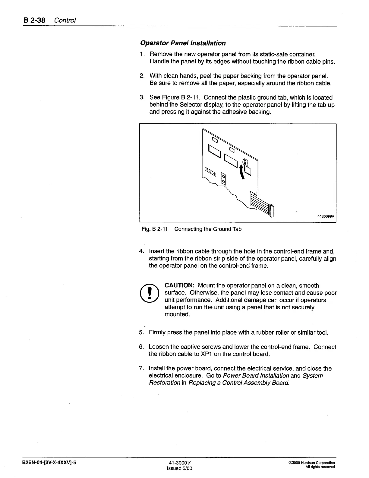
3. See
Figure B
2-11. Connect the
plastic ground
tab, which is located
behind the
Selector display, to the operator
panel
by lifting the tab up
and
pressing
it
against the adhesive backing.
4130099A
Fig. B 2-11
Connecting the Ground Tab
4. lnsert
the ribbon cable
through the hole
in
the control-end frame
and,
starting from
the ribbon strip side of
the operator
panel,
carefully
align
the operator
panel
on the control-end frame.
CAUTION: Mount the operator
panel
on a clean, smooth
surface.
Otherwise, the
panel
may lose
contact and cause
poor
unit
performance.
Additional damage
can occur if operators
attempt
to
run
the unit using a
panel
that
is not securely
mounted.
5.
Firmly
press
the
panel
into
place
with
a
rubber
roller or similar tool.
6. Loosen the captive screws
and
lower
the control-end frame.
Connect
the
ribbon
cable to XP1 on the control
board.
7. lnstall the
power
board, connect the
electrical service, and close the
electrical enclosure.
Golo Power Board lnstallation
and System
Restoration
in Replacing a
Control
Assembly
Board.
I
a
82EN-04-[3V-X-4XXVI-5
41-3000v
lssued
5/00
@000 Nordson Corporation
All dghts reserved
 Loading...


