Operation 109
b Disconnect the power cord’s male plug from the power source.
c Disconnect the power cord’s female plug from the power cord receptacles on PSU0 and PSU1.
4 On the expansion chassis (all attached in this configuration) complete the following:
a Turn off (0) the PSU0 power switch and then turn off the PSU1 power switch.
b Disconnect the power cord’s male plug from the power source.
c Disconnect the power cord’s female plug from the power cord receptacles on PSU0 and PSU1.
Powering On the 5U84 System
This section provides the following information:
• Powering On the 5U84 Expansion Chassis
• Powering On the 5U84 RAID Chassis
Powering On the 5U84 Expansion Chassis
To power on the expansion chassis:
CAUTION: Refer to Figure 96 and Figure 97 and verify that all expansion chassis and RAID chassis
power switches are in the off position (0) to ensure none of the chassis power on before needed.
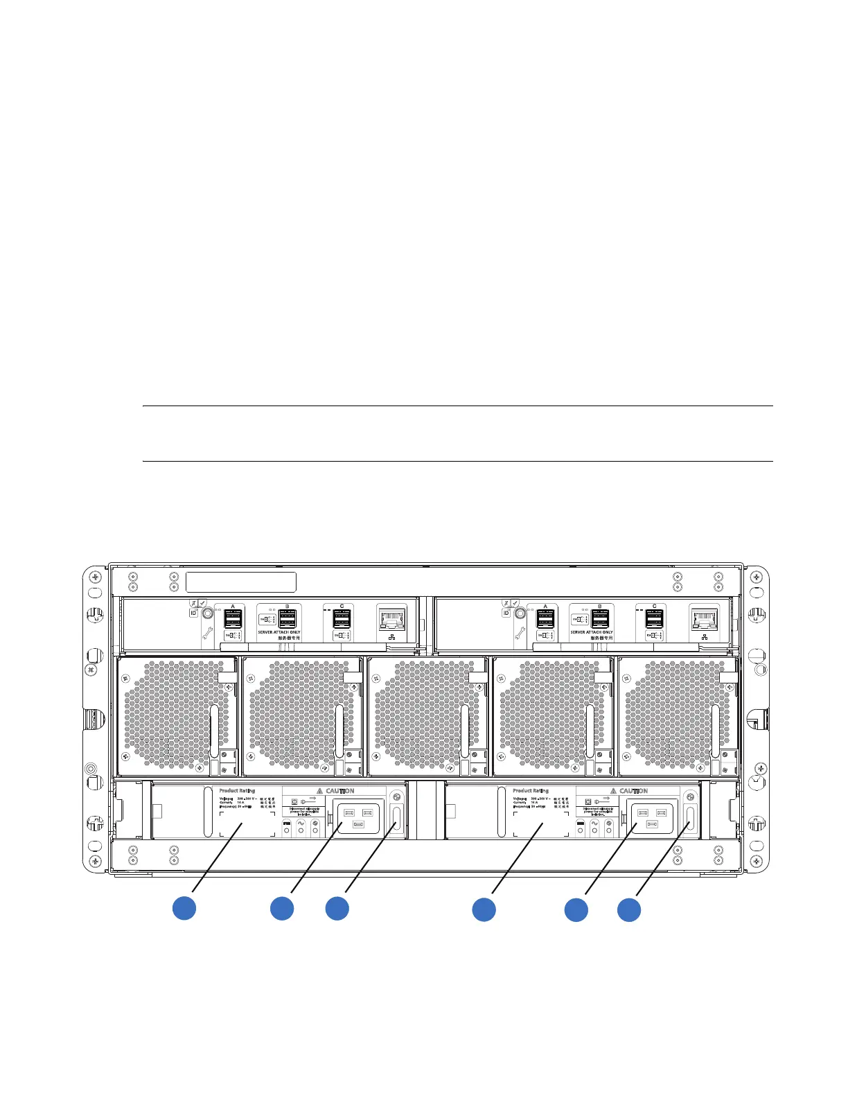
1 Locate the power supply units (PSU0 and PSU1) on the rear of the 5U84 expansion chassis in
Figure 96.
Figure 96 5U84 Expansion Chassis (Rear View)
1
2
1
32
4
6
5
1
PSU0
2
PSU0 Power Receptacle
3
PSU0 Power Switch
4
PSU1
5
PSU1 Power Receptacle
6
PSU1 Power Switch
 Loading...


