System Overview 19
2U12-Drive/2U24-Drive Expansion Chassis Rear View
NOTE: The 2U12-drive and 2U24-drive expansion chassis rear views look identical. Figure 21
provides an illustration of the chassis rear view.
The top middle slot, Figure 21, is the Expansion IOM A location. The lower middle slot is the
Expansion IOM B location. Both IOMs are shown in the closed/locked position.
Expansion Chassis
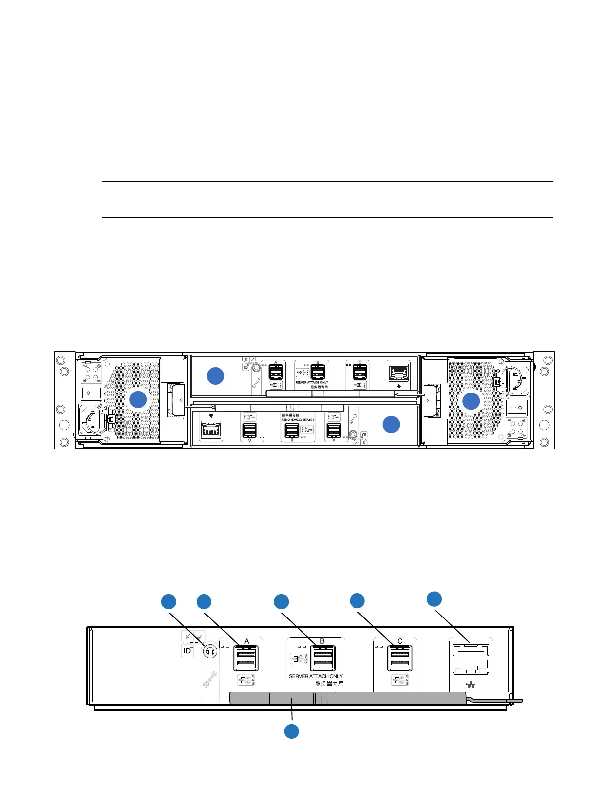
Figure 21 provides a rear view of the 2U12-drive or 2U24-drive expansion chassis rear panel. The
expansion chassis attaches to the RAID chassis for additional storage.
Figure 21 2U12/2U24-Drive Expansion Chassis Rear View
Expansion Chassis IOM
Figure 22 provides a rear view of the expansion chassis IOM used in the 2U12-drive or 2U24-drive
systems. Ports A/B/C ship configured with 12Gb/s HD mini-SAS (SFF-8644) external connectors.
Figure 22 Expansion Chassis IOM
1
SAS Port
2
Ethernet Port
3
USB Port
4
Serial Ports (service only)
5
Reset
6
CNC Port 0
7
CNC Port 1
8
CNC Port 2
9
CNC Port 3
10
Lock/Release Handle
1
2
3
4
1
IOM A
2
IOM B
3
PSU0
4
PSU1
2 3
4
1
5
 Loading...


