208 QXS G2 Hardware Installation and Maintenance Guide
Be mindful of the intricacies associated with RAID controllers and/or expansion IOMs before engaging
in replacement. Key considerations pertaining to controllers and/or expansion IOM replacement in 2U
chassis apply equally to 5U chassis. Please familiarize yourself with these topics before replacing a
controller or expansion IOM in the 5U84 chassis:
IMPORTANT: The QXS-G2-412, QXS-G2-424, and QXS-G2-484 systems support dual-controller
configuration only. If a partner controller fails, the storage system will fail over and run on a single
controller module until the redundancy is restored. A controller module must be installed in each slot
to ensure sufficient air flow through the chassis during operation.
• Before You Begin on page 180
• Configuring Partner Firmware Update on page 180
• Verifying Component Failure on page 181
• Stopping I/O on page 181
• Shutting Down a Controller Module on page 182
Removing a 5U84 RAID Controller or Expansion IOM
IMPORTANT: Considerations for removing controller modules:
• In a dual-controller environment, you may hot-swap a single controller module in an
operational chassis, provided you first shut down the faulty controller using the disk
management utility (GUI) or the CLI.
• In a dual-controller environment—if replacing both controller modules—you must adhere to
the instructions provided in Before You Begin on page 180.
• Do not remove a faulty module unless its replacement is on-hand. All modules must be in place
when the system is in operation.
Comply with all ESD precautions. Refer to ESD Precautions on page 165 for additional information.
Illustrations in the controller module replacement procedures show rear panel views of the chassis,
and the controllers/expansion IOMs are properly aligned for insertion into the applicable slots.
1 Verify that you have successfully shut down the controller module using the disk management
utility (GUI) or the CLI.
2 Locate the chassis whose UID LED (Ops panel on chassis left front ear) is illuminated, and within
the chassis, locate the controller module whose OK to Remove LED is blue (rear panel).
3 Disconnect any cables connected to the controller or expansion IOM.
Label each cable to facilitate re-connection to the replacement controller or expansion IOM.
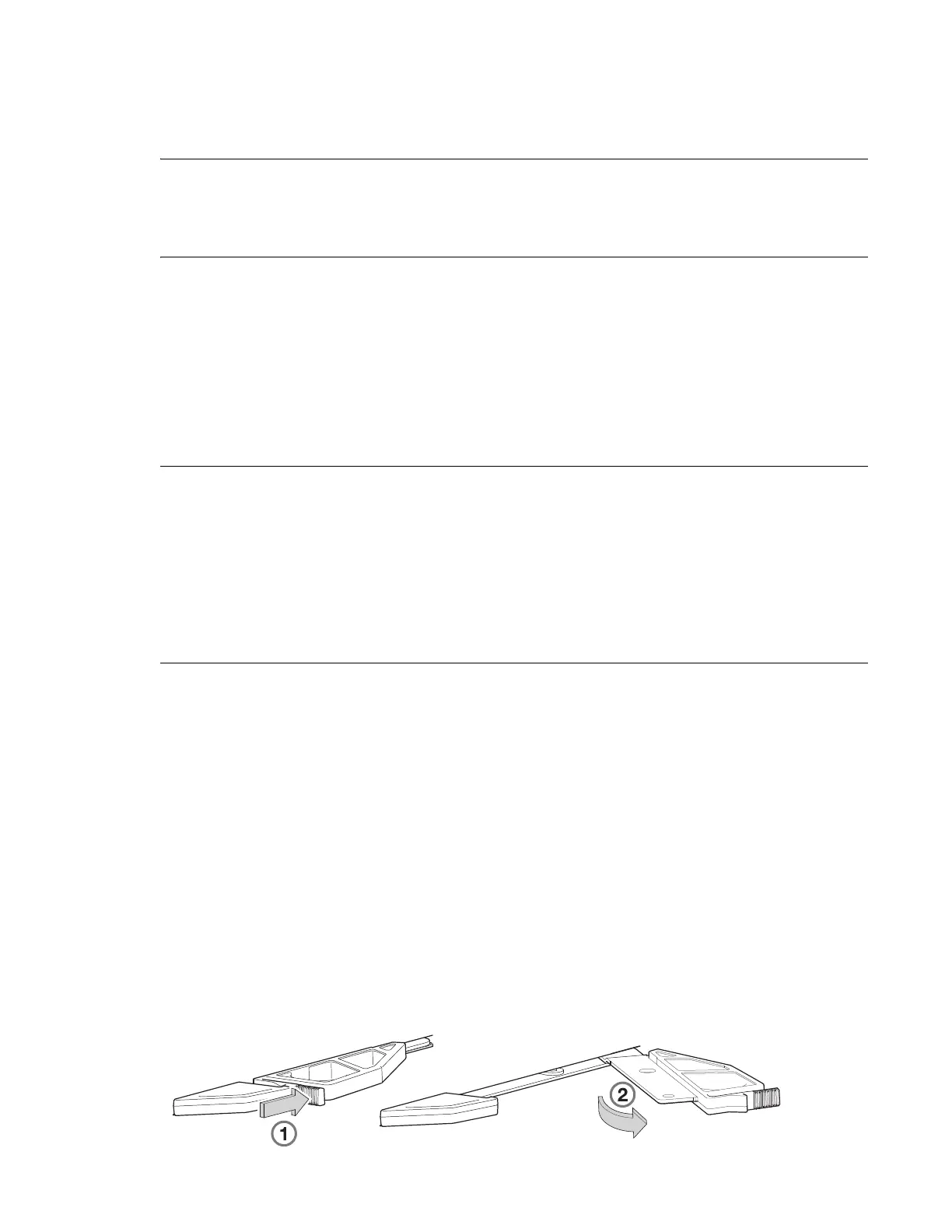
4 Grasp the module latch between the thumb and forefinger, and squeeze the flange and handle
together to release the latch handle from its docking member (detail No.1), and swing the latch
out to release the controller or expansion IOM from its seated position (detail No.2) as shown in
Figure 173 and Figure 174 on page 209.
Figure 173 Controller or Expansion IOM Latch Operation
 Loading...


