Troubleshoot/Problem Solving 121
QXS-G2-312/324 Chassis RAID Chassis Controller LEDs
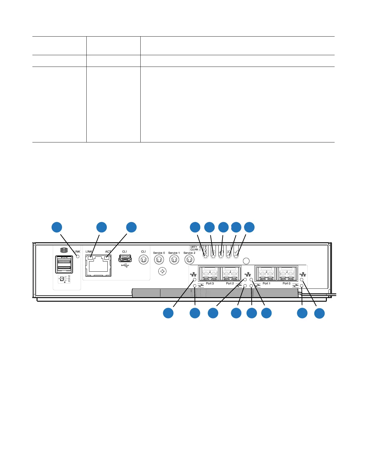
Figure 102 provides an illustration of the RAID chassis controller LEDs. This is a representative
example of the controller LEDs.The controller is identical in the QXS-G2-312 and QXS-G2-324 systems
(2 host ports).
Figure 101 CNC (FC and 10GbE SFPs) Controller LEDs
Off On Power control circuit failure
Off On RAID array status
The events in which the controller can set this notification are:
• Disk group rebuild in progress
• Disk group consistency check
• Do not remove device
• Disk in failed disk group
• Aborted disk group reconstruction
Ta b l e 1 4 2U Drive LED States
Drive LED
(Green)
Drive LED
(Amber)
Status
4
5679
2 2
2
10
10
2
1
8 3
1
1
1
LED
Description Definition
1
Host 4/8/16Gb FC
1
Link
Status/Link Activity
Off — No link detected.
Green — The port is connected and the link is up.
Blinking green — The link has I/O or replication activity.
2
Host 10GbE iSCSI
2,3
Link Status/Link
Activity
Off — No link detected.
Green — The port is connected and the link is up.
Blinking green — The link has I/O or replication activity.
3
OK Green — The controller is operating normally.
Blinking green — System is booting.
Off — The controller module is not OK, or is powered off.
4
Fault Off — The controller is operating normally.
Amber — A fault has been detected or a service action is required.
Blinking amber — Hardware-controlled power-up or a cache flush or restore
error.
 Loading...


