134 QXS G2 Hardware Installation and Maintenance Guide
Thermal Alarm
Tabl e 2 7 provides thermal alarm faults and the recommended actions.
Troubleshooting 5U Chassis
Tabl e 2 8 describes common problems that can occur with your storage system, together with
possible solutions. For all of the problems listed in Table 2 8 , the Module Fault LED on the Ops panel
will light amber to indicate a fault. See 5U Chassis Ops Panel LEDs on page 128. All alarms will also
report via SES.
For information about replacing modules, see 5U84 Chassis CRU Replacement on page 190.
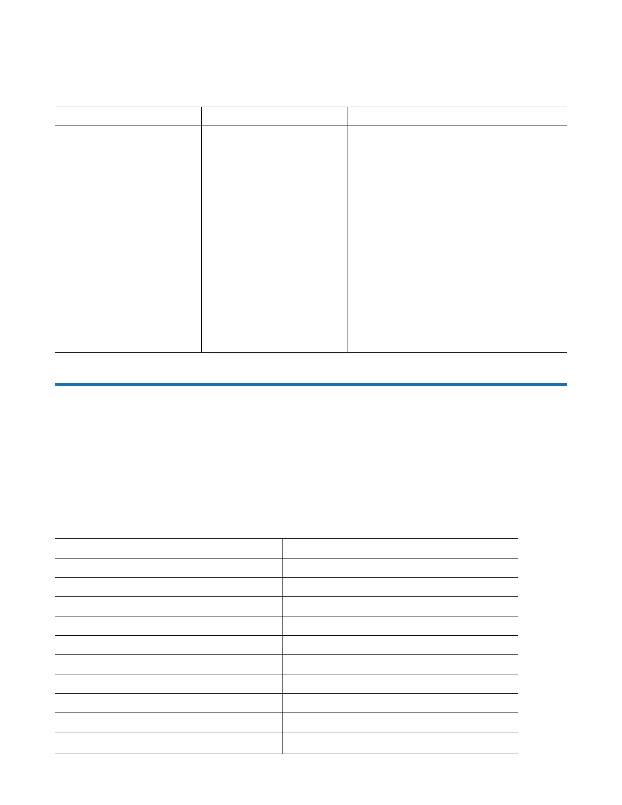
Ta b l e 2 7 Thermal Alarm Faults
Symptom Cause Recommended Action
1 Ops panel Module Fault
LED is amber.
2 Fan Fail LED is illuminated
on one or more PSUs.
Internal temperature exceeds
a preset threshold for the
chassis.
1 Verify that the local ambient environment
temperature is within the acceptable
range. See also QXS 2U/5U Environmental
Requirements on page 217.
2 Check the installation for any airflow
restrictions at either the front or back of
the chassis. A minimum gap of 25 mm (1")
at the front and 50 mm (2") at the rear is
recommended.
3 Check for restrictions due to dust build-up.
Clean as appropriate.
4 Check for excessive re-circulation of heated
air from rear to front. Use of the chassis in
a fully enclosed rack is not recommended.
5 If possible, shut down the chassis and
investigate the problem before continuing.
Ta b l e 2 8 5U Alarm Conditions
Status Severity
PSU alert–loss of DC power from a single PSU Fault–loss of redundancy
Cooling module fan failure Fault–loss of redundancy
SBB I/O module detected PSU fault Fault
PSU removed Configuration error
Chassis configuration error (VPD) Fault–critical
Low temperature warning Warning
High temperature warning Warning
Over-temperature alarm Fault–critical
Under-temperature alarm Fault–critical
I
2
C bus failure
Fault–loss of redundancy
 Loading...


