Module Remove and Replace 175
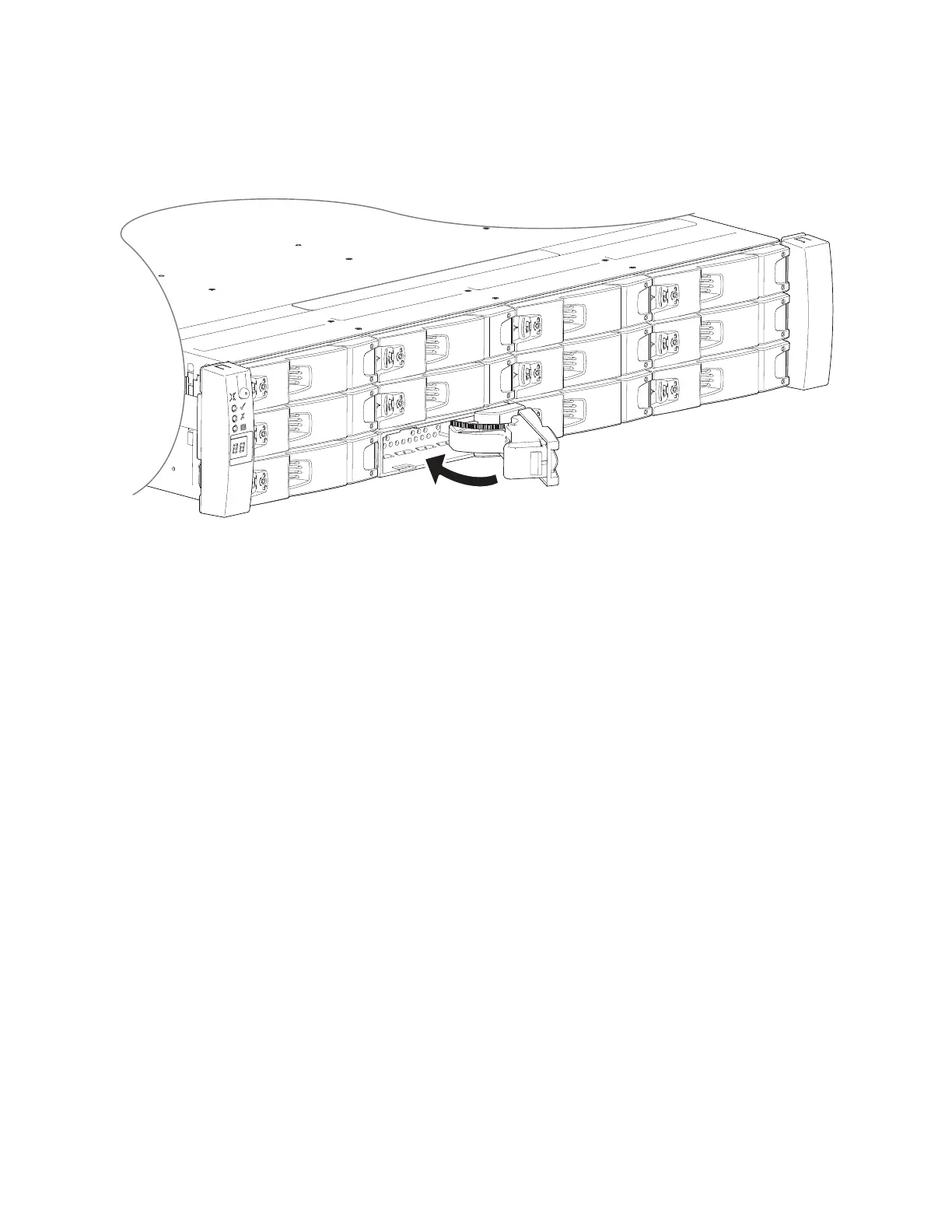
a The camming foot on the carrier will engage into a slot in the chassis.
b Continue to push firmly until the handle fully engages.
c You should hear a click as the latch handle engages and holds the handle closed.
Figure 137 Installing a 3.5” LFF Drive Carrier Module-2
5 Using the management interfaces (the disk management utility (GUI) or CLI), verify whether the
health of the new drive is OK.
a Verify that the Green Drive LED is on/blinking.
b Verify that Ops panel states show no amber module faults.
Using the Anti-Tamper Locks
The 3.5” LFF and 2.5” SFF drive modules provide anti-tamper locks. Refer to Figure 138 on page 176
when using this procedure.
1 Carefully put the T10 lock key into the cutout in the handle.
• The 3.5” LFF drive module is shown in Figure 138 on page 176.
• On 2.5” SFF drive modules, the socket is located between the latch and the carrier handle
(Figure 139 on page 176).
• The lock socket mechanism is identical on both modules.
2 Position the key into its socket.
3 Perform one of the following actions to either activate or deactivate the anti-tamper lock:
aLock: Rotate the key in a clockwise direction until the indicator is visible in the aperture beside
the key.
b Unlock: Rotate the key in a counterclockwise direction until the indicator is visible in the
aperture beside the key.
 Loading...


