System Overview 35
Logical Status LED (amber)
This LED indicates a change of status or fault from something other than the chassis management
system. This may be initiated from the controller module or an external HBA. The indication is
typically associated with a DDIC and LEDs at each disk position within the drawer, which help to
identify the DDIC affected.
Drawer Fault LEDs (amber)
This LED indicates a disk, cable, or sideplane fault in the drawer indicated: Top (Drawer 0) or Bottom
(Drawer 1).
PSUs – 2U CRU
The 2U12 and 2U24 use the same type of PSUs. AC-DC power is provided by up to two auto-ranging
power PSUs with integrated axial cooling fans. The RAID controllers and expansion IOMs control fan
speed.
PSU Features
The 580W PSU voltage operating range is nominally 100V–240V AC, and operates at 50–60 Hz input
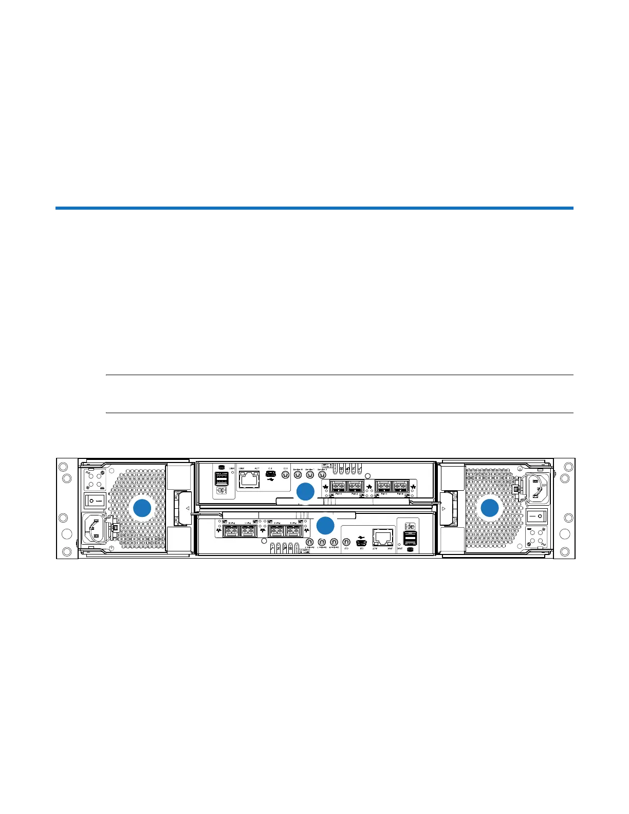
frequency. Figure 41 provides a representative illustration of the PSUs in a 2U chassis. PSU0 and PSU1
are installed 180 degrees as compared to each other (callouts 3 and 4).
NOTE: Controller A and Controller B are also installed 180 degrees as compared to each other
(callouts 1 and 2).
Figure 40 2U12-Drive/2U12-Drive RAID Chassis (4 FC/iSCSI ports)
4
1
2
3
1
Controller A
2
Controller B
3
PSU0
4
PSU1
 Loading...


