Module Remove and Replace 211
Before You Begin
CAUTION: Do not remove the chassis until you have received the replacement chassis.
Comply with all ESD precautions. Refer to ESD Precautions on page 165 for additional information.
1 Schedule down time that will allow for shutdown; sixty minutes of replacement work; and restart.
2 Verify the existence of a known/good backup of the system.
3 Record system settings for future use and label all cables.
4 Prepare a suitable static-protected work environment to accommodate chassis replacement.
Verifying Component Failure
The RAID chassis or expansion chassis CRU includes the chassis metal housing, the module runner
system, the integrated Ops panel, chassis drawers for holding DDICs, and the assembled/installed
midplane, sideplane, and baseplane PCBs that connect various components within the chassis. See
Figure 176 and Figure 177 for a pictorial view of the 5U84.
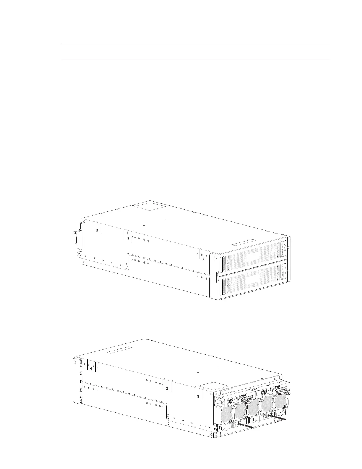
Figure 176 provides a front view of the
5U84-drive system.
Figure 176 5U84-Drive System-Front View
Figure 177 provides a rear view of the 5U84-drive system. The 5U84 RAID chassis has dual-controllers
(4-port FC/iSCSI model shown) installed.
Figure 177 5U84-Drive System-Rear View
 Loading...


