16 QXS G2 Hardware Installation and Maintenance Guide
• Two 580W, 100–240V AC PSUs (with power cords). See also Figure 41 on page 36.
• Two RAID controllers (with Ethernet cable) or two expansion IOMs: 2 x SBB-compliant interface
slots.
• Up to 12 or 24 drive modules in the 2U chassis.
• Where appropriate the drive carriers will include an Interposer card.
• See also Chassis Variants on page 14. drive blanks must be installed in all empty drive slots.
• A rail kit for rack mounting.
NOTE: The following figures show component locations–together with CRU slot indexing–relative to
2U chassis front and rear panels.
2U12-Drive Chassis Front View
Integers on the drives indicate drive slot numbering sequence (0-11). Figure 15 provides a front view
of the 2U12-drive chassis.
Figure 15 2U12-Drive Chassis Front View
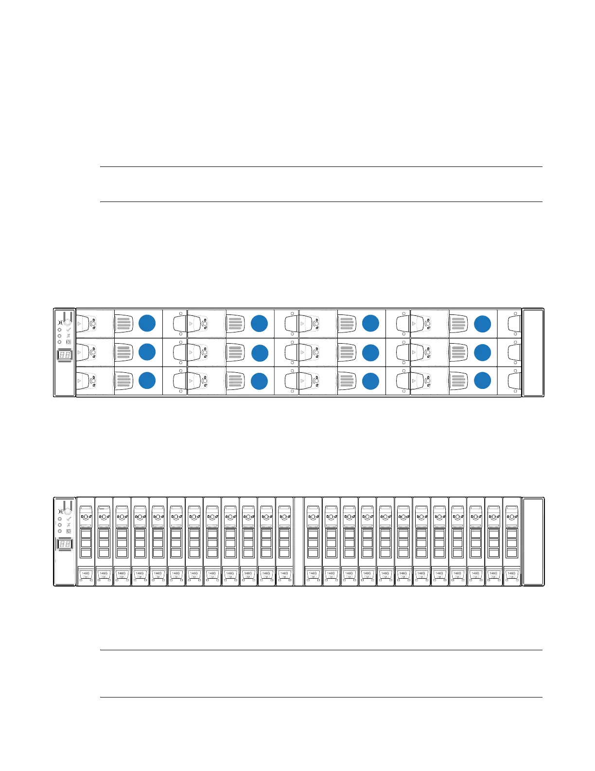
2U24-Drive Chassis Front View
Integers on the drives indicate drive slot numbering sequence (0-23). Figure 16 provides a front view
of the 2U24-drive chassis.
Figure 16 2U24-Drive Chassis Front View
QXS-G2-312 and QXS-G2-324 RAID Chassis Rear View (2-Host Port
Controllers)
NOTE: The 2U12-drive and 2U24-drive RAID chassis (2-host port controllers) rear views look
identical.
Figure 19 provides an illustration of the chassis rear view with two CNC controllers (2 FC/iSCSI ports).
01
2345
6
78
9
10 11 12 13 14 15
16 17
18
19 20
21 22
23
 Loading...


