Module Remove and Replace 169
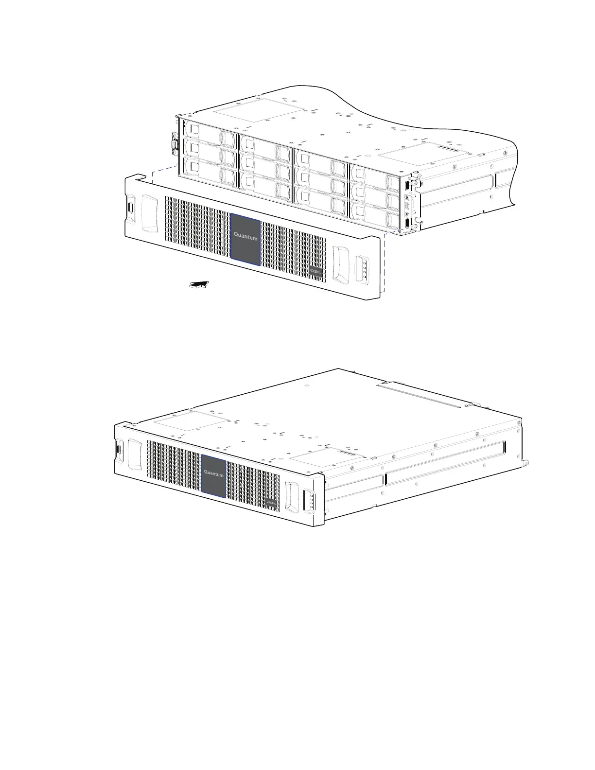
3 Orient the bezel assembly to align its back side with the front face of the chassis as shown in
Figure 129.
Figure 129 Orienting Bezel
4 Face the front of the chassis, and while supporting the base of the bezel, gently slip the integrated
ear covers onto the push-fit ball studs, taking care to guide the LED indicators through bezel
openings.
Figure 130 Installed Bezel
5 Gently push-fit the two ear cover areas of the bezel onto the ball studs to secure the bezel in
place.
Replacing a 2U PSU
This section provides procedures for replacing a failed PSU. Illustrations in PSU replacement
procedures show rear panel views of the chassis, with the PSU properly oriented for insertion into the
rear panel of the chassis.
A single PSU is sufficient to maintain operation of the chassis. You need not halt operations and
completely power-off the chassis when replacing only one PSU; however, a complete orderly
shutdown is required if replacing both units simultaneously.
 Loading...


