Before Replacing Parts
J012/J013/J014 3-6 SM
3.1.3 PROCEDURE SUMMARY
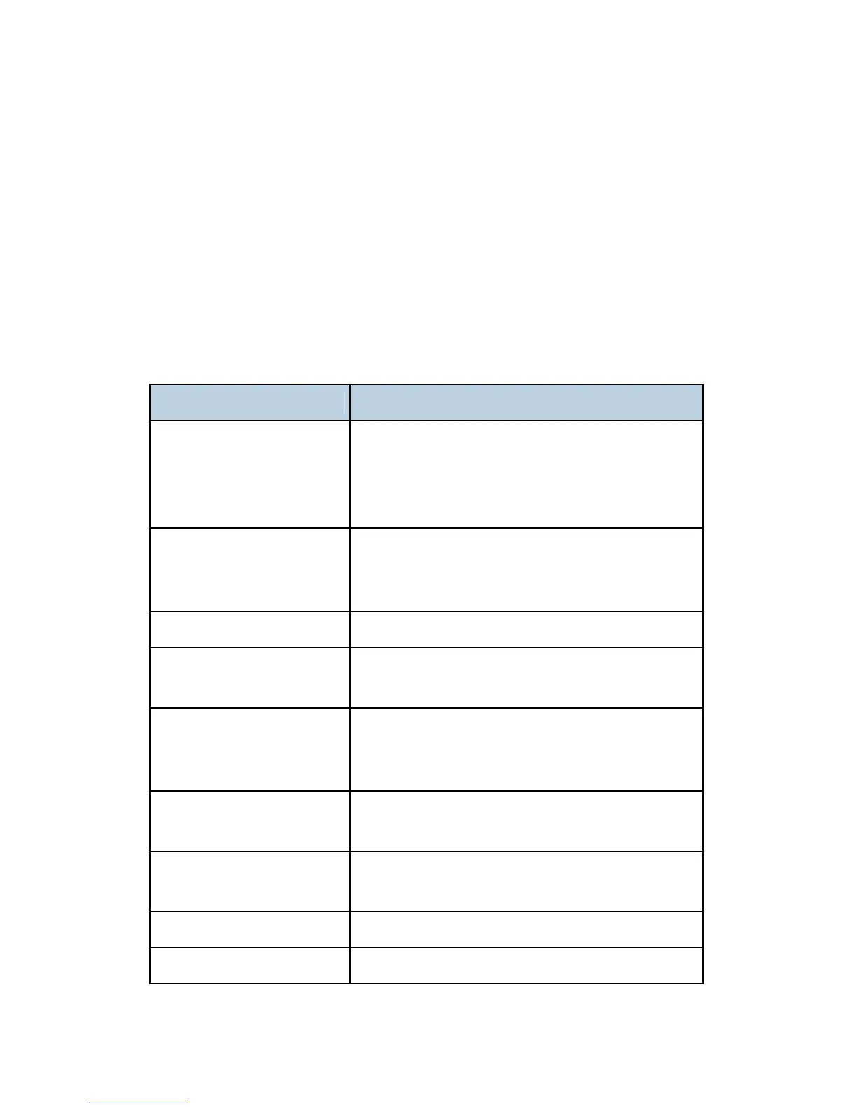
The reference table below is a list of components in alphabetic order.
The left column lists the item to be removed.
The right column tells you what other parts must be removed before the item in the left
column can be removed. Before you use this table for reference, you must be familiar
with the procedures described "Common Procedures" (the next section).
There is a detailed description in this service manual for every item listed in the left
column. Be sure to refer to the appropriate section of the manual for more details.
No prior procedures are required for items marked "---" in the right column.
To remove: First, remove in this order:
1st Registration Sensor 1) Platen or ADF., 2) Scanner to Full Upright, 3) Paper
Cassette, Output Tray, 4) Right Front Cover, 5) Right
Cover, 6) Right Inner Cover, 7) Left Cover, 8) Front
Cover
2nd Registration Sensor 1) Platen or ADF., 2) Scanner to Full Upright, 3) Paper
Cassette, Output Tray, 4) Right Cover, 5) Left Cover, 6)
Scanner Unit, 7) Rear Cover
ADF. (J013/J014) ---
Air Release Solenoid 1) Platen or ADF., 2) Scanner Unit to Upright, 3) Paper
Cassette, Output Tray, 4) Right Cover
CTL Board, NVRAM 1) Platen or ADF., 2) Scanner to Full Upright, 3) Paper
Cassette, Output Tray, 4) Right Cover, 5) Left Cover, 6)
Scanner Unit, 7) Rear Cover
Carriage Position Sensor 1) Platen or ADF., 2) Scanner to Full Upright, 3) Paper
Cassette, Output Tray, 4) Right Cover
Cleaning – Feed Roller 1) Platen or ADF., 2) Scanner to Full Upright, 3) Paper
Cassette, Output Tray
Cleaning – Flushing Gate 1) Platen or ADF., 2) Scanner to Full Upright
Cleaning – Friction Pad ---
 Loading...