Home
Siemens
Portable Generator
6SL3120-2TE21-0AA3
Siemens 6SL3120-2TE21-0AA3 User Manual
5
of 1
of 1 rating
499 pages
Give review
Manual
Specs
To Next Page
To Next Page
To Previous Page
To Previous Page
Loading...
Line Modu
les Book
size
4.4
Activ
e Line M
odules
wit
h cold pl
ate
Booksize Power Units
200
Manual
,
(GH2), 04/2014
,
6S
L3097
-
4AC00
-
0BP6
4.4.2
Interface
descri
ption
4.4.2.1
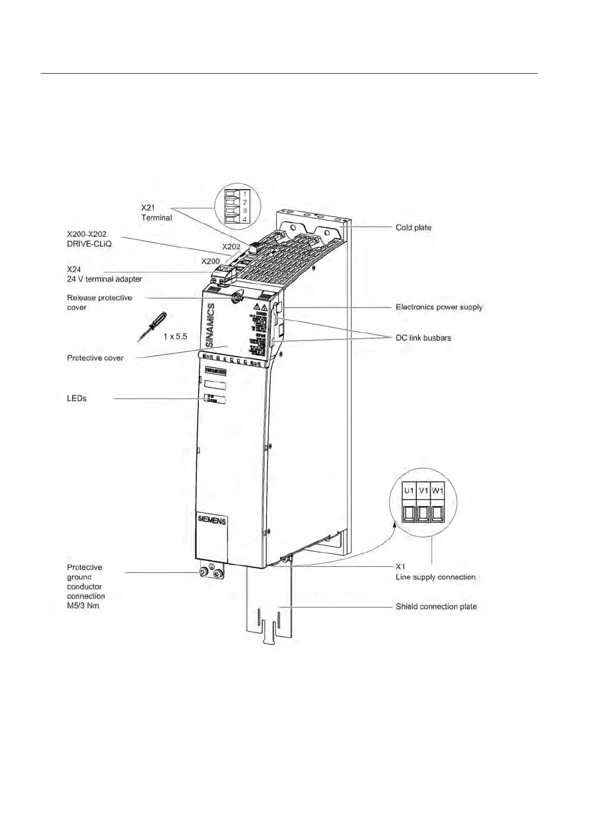
Overview
Figure
4-
30
Interface
overvi
ew, Active
Line M
odule with
cold plate (
exam
ple: 16 kW)
Artisan Technology Group - Quality Instrumentation ... Guaranteed | (888) 88-SOURCE | www.artisantg.com
200
202
Table of Contents
Preface
6
Table of Contents
12
Fundamental Safety Instructions
26
General Safety Instructions
26
Safety Instructions for Electromagnetic Fields (EMF)
29
Handling Electrostatic Sensitive Devices (ESD)
30
Industrial Security
30
Residual Risks of Power Drive Systems
31
System Overview
34
Field of Application
34
Platform Concept and Totally Integrated Automation
35
Introduction
37
SINAMICS S120 Components
39
Overview of Line Modules
41
Overview of Motor Modules
44
System Data
46
Derating as a Function of the Installation Altitude and Ambient Temperature
48
Line Connection and Line-Side Power Components
50
Introduction
50
Information on the Disconnector Unit
51
Overcurrent Protection by Means of Line Fuses and Circuit Breakers
52
Line Supply Connection Via Residual-Current Devices
54
Residual-Current Operated Circuit Breakers (RCD)
54
Residual-Current Monitors (RCM)
56
Overvoltage Protection
58
Line Contactors
58
Line Filters
59
Safety Instructions for Line Filters
59
Overview of Line Filters
61
Basic Line Filters for Active Line Modules
63
Description
63
Interface Description
64
Dimension Drawings
65
Technical Data
68
Wideband Line Filter for Active Line Modules
69
Description
69
Interface Description
70
Dimension Drawings
72
Technical Data
76
Basic Line Filter for Basic Line Modules
77
Description
77
Interface Description
78
Dimension Drawings
79
Technical Specifications
81
Basic Line Filter for Smart Line Modules
82
Description
82
Interface Description
83
Dimension Drawings
84
Technical Specifications
86
Line Reactors
87
Safety Instructions for Line Reactors
87
Overview of the Line Reactors
89
Line Reactors for Active Line Modules
90
Interface Description
90
Dimension Drawings
93
Technical Data
98
Damping Resistor for HFD Line Reactors
99
Description
99
Safety Instructions for Damping Resistors for HFD Reactors
99
Dimension Drawings
100
Technical Data
103
Wiring with the HFD Line Reactor
104
Line Reactors for Basic Line Modules
105
Interface Description
105
Dimension Drawings
108
Technical Data
111
Line Reactors for Smart Line Modules
112
Interface Description
112
Dimension Drawings
114
Technical Data
117
Active Interface Modules Internal Air Cooling
118
Description
118
Safety Instructions for Active Interface Modules
119
Interface Description
121
Overview
121
Line/Load Connection
124
X121 Temperature Sensor and Fan Control
125
X124 Electronics Power Supply
125
Connection Example
126
Dimension Drawings
127
Installation
131
Operation on an Isolated-Neutral System (IT System)
134
Electrical Tests
135
Technical Data
136
Combining Line Reactors and Line Filters
137
Line Connection Variants
138
Ways of Connecting the Line Supply
138
Operating Line Connection Components on the Line Supply
140
Operation of the Line Connection Components Via a Transformer
141
Safety Instructions for Line Connection Components
141
Line Supply Connection Conditions for Line Modules
142
Dimensioning an Isolating Transformer / Autotransformer for Several Loads
143
Operating Line Connection Components Via an Autotransformer
148
Operating Line Connection Components Via an Isolating Transformer
150
Line Modules Booksize
152
Safety Instructions for Line Modules Booksize
152
Active Line Modules with Internal Air Cooling
157
Description
157
Interface Description
158
Overview
158
X1 Line Connection
159
X12 Fan Connection
160
X21 EP Terminals
160
X24 24 V Terminal Adapter
162
X200-X202 DRIVE-Cliq Interfaces
162
Connection Example
163
Meaning of Leds
164
Dimension Drawings
165
Installation
169
Technical Data
171
Characteristics
174
Active Line Modules with External Air Cooling
177
Description
177
Interface Description
178
Overview
178
X1 Line Connection
179
X12 Fan Connection
180
X21 EP Terminals
180
X24 24 V Terminal Adapter
182
X200-X202 DRIVE-Cliq Interfaces
182
Connection Example
183
Meaning of Leds
184
Dimension Drawings
185
Mounting
188
Technical Data
194
Characteristics
197
Active Line Modules with Cold Plate
200
Description
200
Interface Description
201
Overview
201
X1 Line Connection
202
X21 EP Terminals
203
X24 24 V Terminal Adapter
204
X200-X202 DRIVE-Cliq Interfaces
205
Connection Example
206
Meaning of Leds
207
Dimension Drawings
208
Mounting
210
Technical Data
213
Characteristics
215
Active Line Modules Liquid Cooled
218
Description
218
Interface Description
219
Overview
219
X1 Line Connection
220
X21 EP Terminals
220
X24 24 V Terminal Adapter
222
X200-X202 DRIVE-Cliq Interfaces
222
Connection Example
223
Meaning of Leds
224
Dimension Drawing
225
Installation
226
Technical Data
227
Characteristics
229
Basic Line Modules with Internal Air Cooling
232
Description
232
Interface Description
233
Overview
233
X1 Line Connection
234
X2 Braking Resistor Connection
235
X21 EP Terminals
236
X24 24 V Terminal Adapter
238
X200-X202 DRIVE-Cliq Interfaces
238
Connection Examples
239
Meaning of Leds
241
Dimension Drawings
242
Installation
245
Operation on an Isolated-Neutral System (IT System)
246
Technical Data
247
Characteristics
249
Basic Line Modules with Cold Plate
252
Description
252
Interface Description
253
Overview
253
X1 Line Connection
254
X2 Braking Resistor Connection
255
X21 EP Terminals
256
X24 24 V Terminal Adapter
258
X200-X202 DRIVE-Cliq Interfaces
258
Connection Examples
259
Meaning of Leds
261
Dimension Drawings
262
Mounting
265
Operation on an Isolated-Neutral System (IT System)
269
Technical Data
270
Characteristics
272
Smart Line Modules with Internal Air Cooling
275
Description
275
Safety Instructions for Smart Line Modules Booksize
275
Interface Description
277
Overview
277
X1 Line Connection
280
X21 EP Terminals
282
X22 Digital Inputs
285
X24 24 V Terminal Adapter
286
X200-X202 DRIVE-Cliq Interfaces
286
Connection Examples
287
Meaning of Leds
289
Smart Line Modules 5 Kw and 10 Kw
289
Kw to 55 Kw Smart Line Modules
290
Dimension Drawings
291
Installation
295
Technical Data
296
Characteristics
298
Smart Line Modules with External Air Cooling
300
Description
300
Safety Instructions for Smart Line Modules Booksize
300
Interface Description
302
Overview
302
X1 Line Connection
305
X21 EP Terminals
307
X22 Digital Inputs
310
X24 24 V Terminal Adapter
311
X200-X202 DRIVE-Cliq Interfaces
311
Connection Examples
312
Meaning of Leds
314
Smart Line Modules 5 Kw and 10 Kw
314
Kw to 55 Kw Smart Line Modules
315
Dimension Drawings
316
Mounting
320
Technical Data
325
Characteristics
327
Smart Line Modules with Cold Plate
329
Description
329
Safety Instructions for Smart Line Modules Booksize
329
Interface Description
331
Overview
331
X1 Line Connection
332
X21 EP Terminals
333
X22 Digital Inputs
335
X24 24 V Terminal Adapter
335
Connection Example
336
Meaning of Leds
337
Dimension Drawings
338
Mounting
339
Technical Data
341
Characteristics
343
Measuring the Heat Sink Temperature
345
Line Modules Booksize Compact
346
Smart Line Modules Booksize Compact
346
Description
346
Safety Instructions for Smart Line Modules Booksize Compact
346
Interface Description
351
Overview
351
X1 Line Connection
352
X21 EP Terminals
352
X24 24 V Terminal Adapter
354
X200-X202 DRIVE-Cliq Interfaces
354
Connection Example
355
Meaning of the Leds
356
Dimension Drawing
357
Mounting
358
Technical Data
360
Characteristics
362
Motor Modules Booksize
364
Safety Instructions for Motor Modules Booksize
364
Motor Modules with Internal Air Cooling
369
Description
369
Interface Description
370
Overview
370
Motor and Brake Connection
372
X12 Fan Connection
374
X21/X22 EP Terminals/Temperature Sensor
375
X200-X203 DRIVE-Cliq Interface
376
Connection Examples
377
Meaning of Leds
379
Dimension Drawings
380
Installation
385
Technical Data
387
Single Motor Modules
387
Double Motor Modules
389
Characteristics
390
Technical Data for Motor Modules Booksize with 300% Overload
394
Single Motor Modules (300% Overload)
394
Double Motor Modules (300% Overload)
396
Characteristics for Motor Modules Booksize with 300% Overload
398
Motor Module with External Air Cooling
402
Description
402
Interface Description
403
Overview
403
Motor and Brake Connection
405
X12 Fan Connection
407
X21/X22 EP Terminals/Temperature Sensor
408
X200-X203 DRIVE-Cliq Interface
409
Connection Examples
410
Meaning of Leds
412
Dimension Drawings
413
Mounting
418
Technical Data
424
Single Motor Modules
424
Double Motor Modules
427
Characteristics
428
Technical Data for Motor Modules Booksize with 300% Overload
432
Single Motor Modules (300% Overload)
432
Characteristics for Motor Modules Booksize with 300% Overload
436
Motor Modules with Cold Plate
440
Description
440
Interface Description
441
Overview
441
Motor and Brake Connection
443
X21/X22 EP Terminals/Temperature Sensor
445
X200-X203 DRIVE-Cliq Interface
447
Connection Examples
448
Meaning of Leds
450
Dimension Drawings
451
Mounting
455
Technical Data
458
Single Motor Modules
458
Double Motor Modules
460
Characteristics
461
Technical Data for Motor Modules Booksize with 300% Overload
465
Single Motor Modules (300% Overload)
465
Double Motor Modules (300% Overload)
467
Characteristics for Motor Modules Booksize with 300% Overload
469
Motor Modules Liquid Cooled
473
Description
473
Interface Description
474
Overview
474
Motor and Brake Connection
475
X21 EP Terminal/Temperature Sensor
476
X200-X202 DRIVE-Cliq Interface
478
Connection Example
478
Meaning of Leds
479
Dimension Drawing
480
Installation
481
Technical Data
483
Characteristics
484
Motor Modules Booksize Compact
488
Safety Instructions for Motor Modules Booksize Compact
488
Description
492
Interface Description
493
Overview
493
X1/X2 Motor Connection
495
X11/X12 Motor Brake Connection
495
X21/X22 EP Terminals/Temperature Sensor
496
X200-X203 DRIVE-Cliq Interface
498
Connection Example
499
5
Based on 1 rating
Ask a question
Give review
Questions and Answers:
Need help?
Do you have a question about the Siemens 6SL3120-2TE21-0AA3 and is the answer not in the manual?
Ask a question
Siemens 6SL3120-2TE21-0AA3 Specifications
General
Brand
Siemens
Model
6SL3120-2TE21-0AA3
Category
Portable Generator
Language
English
Related product manuals
Siemens 1D Series
45 pages
Siemens Standby Generators
16 pages
Siemens 7XT3300-0 A00 Series
52 pages
Siemens PowerLink 100
54 pages
Siemens SINAMICS S220
320 pages
Siemens 7XT3300-0 A00/DD Series
52 pages

 Loading...


