Line Modules Booksize
4.10 Smart Line Modules with cold plate
Booksize Power Units
332 Manual, (GH2), 04/2014, 6SL3097-4AC00-0BP6
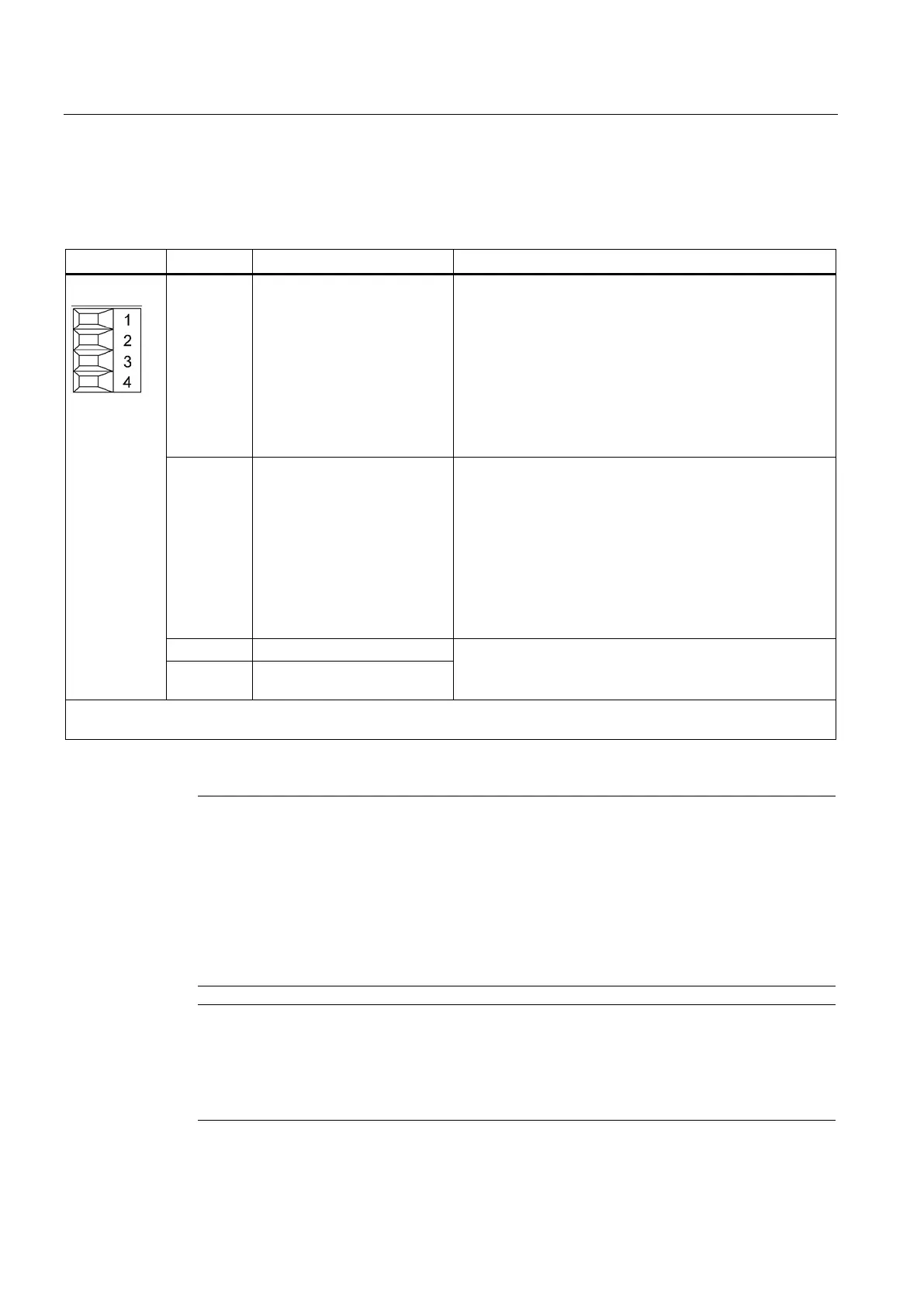
Table 4- 87 X21 EP terminals
1 DO: Ready Feedback signal: Smart Line Module ready
The signal switches to high level when the following
conditions have been met:
• Electronics power supply (X24) OK
• DC link is precharged
• Pulses enabled (X21.3/.4)
• No overtemperature
• No overcurrent switch-off
2 DO: Prewarning
DO: Prewarning
High = no prewarning
Low = prewarning
• Overtemperature warning threshold / I*t
5 kW prewarning: 64° C, disconnection: 69° C
10 kW prewarning: 68° C, disconnection: 73° C
• No regenerative feedback capability due to a line fault
[only monitored when feedback is activated (see
terminal X22.2)]
Voltage 24 V DC
Current consumption: 10 mA
4 EP M (Enable Pulses)
Type: Screw terminal 1 (Page 755)
Max. cross-section that can be connected: 1.5 mm
2
Terminals X21.1 and X21.2
Note
Wiring to a digital input of the Control Unit
Output terminal X21.1 must be wired to a digital input on the CU. The drives supplied with
power from the Smart Line Module have t
o use this signal as a ready signal. This ensures
that a pulse enable can only be issued for the drives (motor or generator operation) when the
infeed is ready.
If interconnection with a digital input on the CU is not possible, the signal must be evaluated
-level control system instead. It is not permissible that the control system sets the
drives to ready until the infeed "Ready" signal is present.
Note
Evaluating the "Prewarning" signal
The "Prewarning" signal at output terminal X21.2 warns
against an overload. If this signal is
set, the control system shuts the drives down before the "Ready" signal switches to "low". If
the "Ready" signal switches to "low", the drive pulses must be suppressed within 4
ms.
Artisan Technology Group - Quality Instrumentation ... Guaranteed | (888) 88-SOURCE | www.artisantg.com

 Loading...


