Valve characteristics Set with parameter value
Inverse equal percentage 25:1 n1-25
Inverse equal percentage 33:1 n1-33
Inverse equal percentage 50:1 n1-50
Freely adjustable FrEE
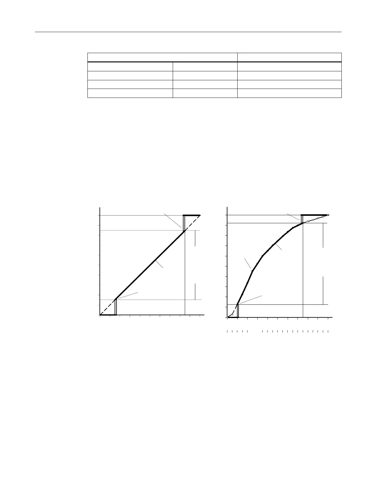
8.3.2.4 '10.SL0' ... '30.SL20' Setpoint turning point
Adjustment range: 0.0 ... 100.0
Purpose: These parameters are used to assign a flow coefficient in units of
5% to each setpoint turning point. The setpoint turning points form
a polyline with 20 linear segments which models the valve charac‐
teristic; see figure below.
Factory setting: 0, 5 ... 95, 100
7LJKWFORVLQJ
([DPSOH
7LJKWFORVLQJ
([DPSOH
&RQWUROUDQJH
6HWSRLQW
Z
<&/6 83
<&83
<&/6 '2
<&'2
6)&7 /LQ
[
[
7LJKWFORVLQJ
([DPSOH
7LJKWFORVLQJ
([DPSOH
&RQWUROUDQJH
6HWSRLQW
6HWSRLQW
LQWHUSRODWLRQSRLQW
([DPSOH
6)&7 )U((
Z
<&/6 83
<&83
6/
6/2
<&/6 '2
<&'2
Setpoint characteristic curves, standardization of manipulated variables, and tight closing
function
Input of the setpoint turning points is only possible if the "'9.SFCT' Setpoint function
(Page 146)" parameter is set to "FrEE". You can only enter one monotone rising characteristic
curve and two consecutive interpolation points must differ by at least 0.2%.
Parameter assignment
8.3 Description of parameters
SIPART PS2 with PROFIBUS PA
Operating Instructions, 05/2019, A5E00127926-AC 147

 Loading...


