F.2.4 PA cable connection for bus connection
1. There are three 3-pin connection sockets on the rear of the 19" slide-in module for
connecting the bus cable.
Commissioning positioner 6DR5910-... and 19" slide-in module (Page 352)
2. Connect up to two 2 PROFIBUS segments PAI_IN or PAII_IN.
3. Connect an additional 19" slide-in module to the same segment using PAI_OUT.
4. Only the PAII_IN I/O has an internal bus termination. If necessary, install an external bus
termination to the segment at PAI. Plug the bus termination into the PAI_OUT connection
socket.
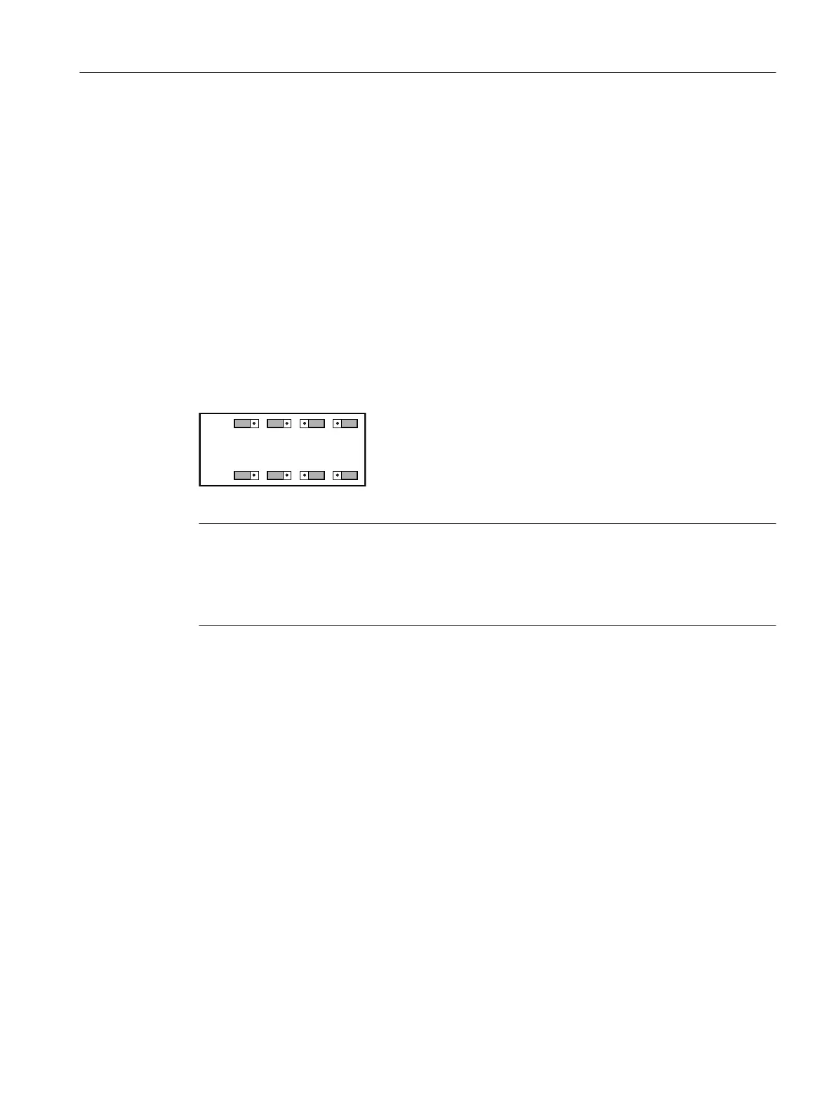
5. Use coding bridges to assign the individual channels to the segments. The coding bridges
are located under the transparent cover of the PA modules.
6. Reconnect the coding bridges in pairs per channel. In the following example, channel CH1
is assigned to the segment PAII and channel CH5 to the channel PAI:
3$
3$
&+
,
,
,,
,,
&+
,
,
,,
,,
&+
,
,
,,
,,
&+
,
,
,,
,,
Figure F-3 Assignment of channels to PAI, PAII via coding bridges
Note
Number of channels and slaves per PROFIBUS line
The maximum number of channels and slaves per PROFIBUS line depends on the data volume
(input and output) and the capacity of the segment. Graphic in Connecting 19" slide-in modules
(Page 358).
Positioner with remote control electronics
F.2 19" slide-in module
SIPART PS2 with PROFIBUS PA
Operating Instructions, 05/2019, A5E00127926-AC 357

 Loading...


