Measuring range Switch block 1 Switch block 2
S1-1 S1-2 S2-1 S2-2 S2-3 S2-4
20 mA OFF OFF ON OFF ON OFF
10 V OFF OFF OFF ON OFF OFF
5.2.4 Option device version M12 connector
This section describes which terminal of the devices and option modules listed below is
connected with the respective pole of the M12 connector.
Note
Technical specifications
Observe the specifications for the electrical data in the certificate and/or in section "Technical
data (Page 281)".
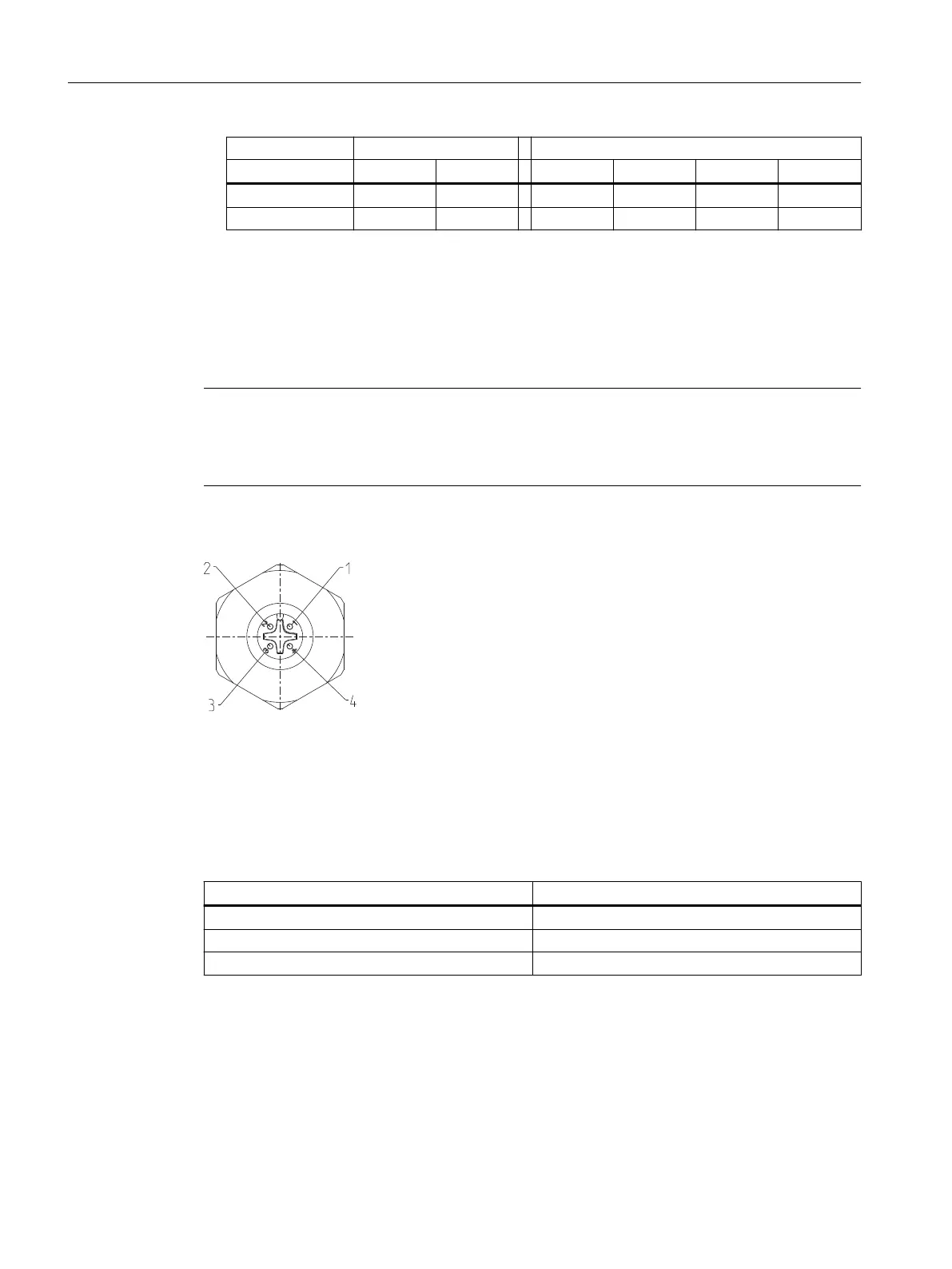
View of the mating side pole pattern
Pole designation Wire color of M12
connector
1 Brown
4 Black
3 Blue
2 White
5.2.4.1 M12 connector in the basic device
You have a positioner 6DR55..-0.R.. or 6DR55..-0.S. In this case the M12 connector is
connected to the bus circuit of the basic electronics.
Table 5-1 Assignment diagram
Bus circuit terminal Pole designation
7 1 - Brown
Shield support of housing 4 - Black
6 3 - Blue
Connect
5.2 Electrical wiring
SIPART PS2 with PROFIBUS PA
90 Operating Instructions, 05/2019, A5E00127926-AC

 Loading...


