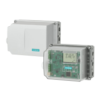
⑧ Alarm module ⑱ Friction clutch adjustment wheel
⑨ Position feedback module ⑲ Wiring diagram on module cover
⑩ Nameplate
Figure 4-13 Installing the optional modules in the standard and intrinsically safe version
Procedure for opening the device
1. Open the positioner.
2. Loosen the four fixing screws of the enclosure cover. Remove the enclosure cover.
3. Disconnect the power supply lines or de-energize the power supply lines.
4. Disconnect all other electrical connections of the device.
5. Loosen the two fixing screws ② of the module cover ①.
6. Remove the module cover ①.
If you install an option module, proceed as described for the respective option modules. For slot
initiator alarm module (SIA), mechanical limit switch module, internal non-contacting sensor
module and EMC filter module, remove the basic electronics.
If you replace the basic electronics, a pneumatic block or pressure sensor module, proceed as
described in the respective chapters under "Service and maintenance (Page 241)".
4.5.1.2 Closing the standard and and intrinsically safe version
The legend numbers refer to the figure in "Opening the standard and and intrinsically safe
version (Page 53)"
1. Now start with the assembly. Place on the module cover ①. Make sure that the ribbon cable
is not trapped.
2. Turn the fixing screws ② counterclockwise until they noticeably engage in the thread pitch.
3. Carefully tighten both fixing screws ② in a clockwise direction.
The module cover protects and locks the optional modules mechanically.
Note
Untimely wear
The module cover is fastened using self-tapping screws, one screw for the base plate and
one screw for the valve.
● In order to avoid premature wear of the base plate and valve, proceed as described here.
4. Connect the power supply lines or supply the power supply lines with voltage.
5. Put on the enclosure cover.
6. Tighten the fixing screws of the enclosure cover.
Installing/mounting
4.5 Installing the optional modules
SIPART PS2 with PROFIBUS PA
Operating Instructions, 05/2019, A5E00127926-AC 55

 Loading...


